Dynamics of Single-Axis Drive Systems
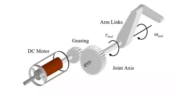
DC motors and other types of actuators are used to drive individual axes of a robotic system. a schematic diagram of a single-axis drive system consisting of a DC motor, a gear head, and arm links1 . An electric motor, such as a DC motor, produces a relatively small torque and rotates at a high speed, whereas a robotic joint axis in general rotates slowly, and needs a high torque to bear the load. In other words, the impedance of the actuator:
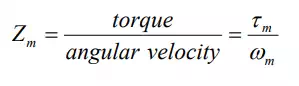
is much smaller than that of the load.
Joint axis drive system
Although a robotic system has multiple axes driven by multiple actuators having dynamic interactions, we consider behavior of an independent single axis in this section, assuming that all the other axes are fixed.
To fill the gap we need a gear reducer, as shown in Figure 2.2.1. Let r > 1 be a gear reduction ratio (If d1 and d2 are diameters of the two gears, the gear reduction ratio is ). The torque and angular velocity are changed to:
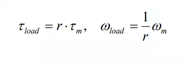
where load τ and ωload are the torque and angular velocity at the joint axis, as shown in the figure. Note that the gear reducer of gear ratio r increases the impedance r 2 times larger than that of the motor axis Zm:
ω mis the time rate of change of angular velocity, i.e. the angular acceleration. Let be the inertia of the arm link about the joint axis, and b the damping coefficient of the bearings supporting the joint axis. Considering the free body diagram of the arm link and joint axis yields
Note that the effective inertia of the motor rotor is r 2 times larger than the original value when reflected to the joint axis. Likewise, the motor constant becomes r 2 times larger when reflected to the joint axis. The gear ratio of a robotic system is typically 20 ~ 100, which means that the effective inertia and damping becomes 400 ~ 10,000 times larger than those of the motor itself. mI
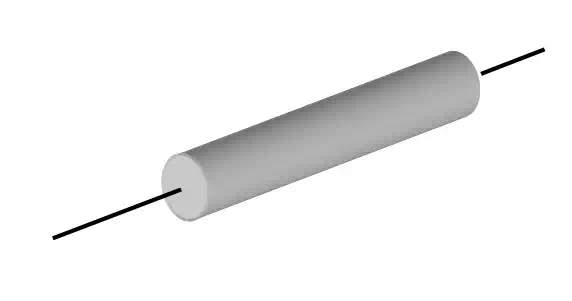
For fast dynamic response, the inertia of the motor rotor must be small. This is a crucial requirement as the gear ratio gets larger, like robotics applications. There are two ways of reducing the rotor inertia in motor design. One is to reduce the diameter and make the rotor longer. The other is to make the motor rotor very thin, like a pancake.
Long and slender
Pancake
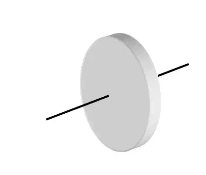
Most robots use the long and slender motors as Figure (a), and some heavy-duty robots use the pancake type motor. a pancake motor by Mavilor Motors, Inc.
Assuming that the angular velocity of a joint axis is approximately zero, obtain the optimal gear ratio r in eq.(7) that maximizes the acceleration of the joint axis.
Power Electronics
Performance of servomotors used for robotics applications highly depends on electric power amplifiers and control electronics, broadly termed power electronics. Power electronics has shown rapid progress in the last two decades, as semiconductors became faster, more powerful, and more efficient. In this section we will briefly summarize power electronics relevant to robotic system development.
Pulse width modulation (PWM)
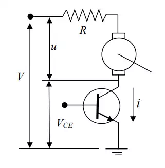
In many robotics applications, actuators must be controlled precisely so that desired motions of arms and legs may be attained. This requires a power amplifier to drive a desired level of voltage (or current indirectly) to the motor armature, as discussed in the previous section. Use of a linear amplifier (like an operational amplifier), however, is power-inefficient and impractical, since it entails a large amount of power loss. Consider a simple circuit consisting of a single transistor for controlling the armature voltage. Let V be the supply voltage connected to one end of the motor armature. The other end of the armature is connected to the collector of the transistor. As the base voltage varies the emitter-collector voltage varies, and thereby the voltage drop across the motor armature, denoted u in the figure, varies accordingly. Let i be the collector current flowing through the transistor. Then the power loss that is dissipated at the transistor is given by
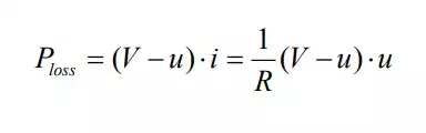
where R is the armature resistance. plots the internal power loss at the transistor against the armature voltage. The power loss becomes the largest in the middle, where half the supply voltage V/2 acts on the armature. This large heat loss is not only wasteful but also harmful, burning the transistor in the worst case scenario. Therefore, this type of linear power amplifier is seldom used except for driving very small motors.
Analogue power amplifier for driving the armature voltage
Power loss at the transistor vs The armature voltage.

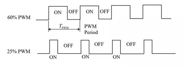
An alternative is to control the voltage via ON-OFF switching. Pulse Width Modulation, or PWM for short, is the most commonly used method for varying the average voltage to the motor. it is clear that the heat loss is zero when the armature voltage is either 0 or V. This means that the transistor is completely shutting down the current (OFF) or completely admitting the current (ON). For all armature voltages other than these complete ON-OFF states, some fraction of power is dissipated in the transistor. Pulse Width Modulation (PWM ) is a technique to control an effective armature voltage by using the ON-OFF switching alone. It varies the ratio of time length of the complete ON state to the complete OFF state. Figure 2.3.3 illustrates PWM signals. A single cycle of ON and OFF states is called the PWM period, whereas the percentage of the ON state in a single period is called duty rate. The first PWM signal is of 60% duty, and the second one is 25 %. If the supply voltage is V=10 volts, the average voltage is 6 volts and 2.5 volts, respectively.
The PWM period is set to be much shorter than the time constant associated with the mechanical motion. The PWM frequency, that is the reciprocal to the PWM period, is usually 2 ~ 20 kHz, whereas the bandwidth of a motion control system is at most 100 Hz. Therefore, the discrete switching does not influence the mechanical motion in most cases.
Pulse width modulation
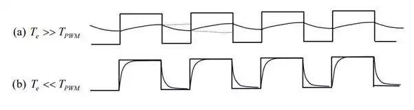
As modeled in eq.(2.1.4), the actual rotor windings have some inductance L. If the electric time constant the is much larger than the PWM period, the actual current flowing to the motor armature is a smooth curve, as illustrated. In other words, the inductance works as a low-pass filter, filtering out the sharp ON-OFF profile of the input voltage. In contrast, if the electric time constant is too small, compared to the PWM period, the current profile becomes zigzag, following the rectangular voltage profile, as shown in Figure 2.3.4-(b). As a result, unwanted high frequency vibrations are generated at the motor rotor. This happens for some types of pancake motors with low inductance and low rotor inertia.
Current to the motor is smoothed due to inductance