Robotic Arm
Servomotor Building Blocks for Robotics
The servomotor brackets discussed in this chapter will allow you to create various servomotor robots and projects.
Servomotors are ideal for powering robots. They are readily available in many sizes, are inexpensive, provide powerful torque for their size and weight, and are positional. The output shafts on most hobby servomotors are guaranteed positional between 0° and 90°. Most servomotors’ output shaft range extends past 90°, coming close to 180°.
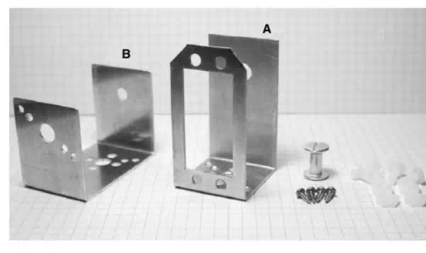
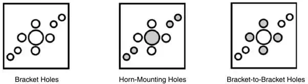
The servomotor bracket components are shown in Fig. 12.1. Each of the aluminum U brackets that make up the assembly has multiple holes for connecting a standard Hi Tec servomotor horn as well as bottom and top holes for connecting U brackets and assemblies to one another.
The servomotor horns used on these servomotor brackets are included with all the compatible Hi Tec servomotors, such as HS322, HS425, HS475, and HS35645. These brackets may also be used with similarsize Futaba servomotors, but you may have to purchase the horns separately.
Each servomotor bracket assembly consists of the following components: two aluminum U brackets, labeled A and B, one binding head post screw, four 632 plastic machine screws with nuts, and four sheet metal screws for mounting a servomotor horn. When assembled with a compatible servomotor (see Fig. 12.2), the bracket becomes a modular component that may be attached to other brackets and components. The bracket allows the top and bottom components to swivel along the axis of the servomotor’s shaft.
By connecting multiple servomotors using the brackets, you can create a variety of robotic designs. In this chapter we will use the brackets to create a five-servo motor robotic arm. In Chap. 13 we use these same brackets to create a bipedal walker robot.
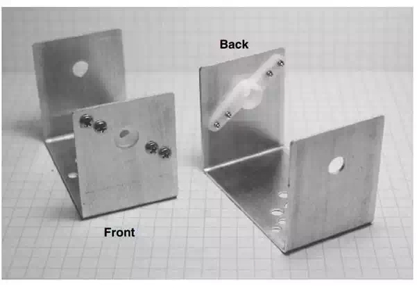
The bottom and top have multiple holes for attaching other brackets or servomotor horns
Servomotor bracket kit.
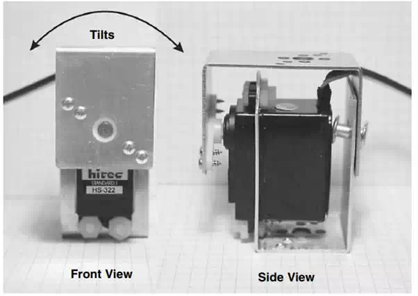
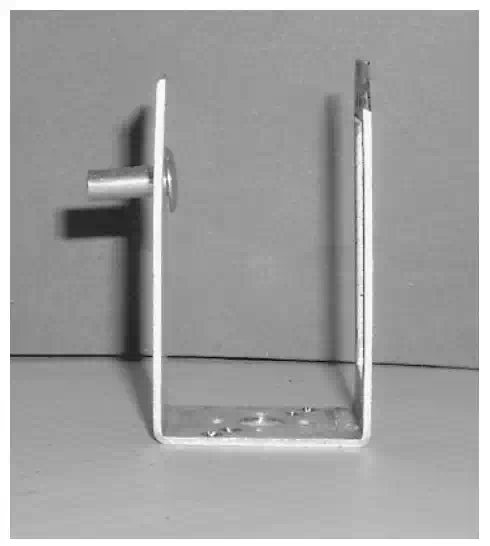
Front and side views of servomotor bracket
Basic Servomotor Bracket Assembly
To assemble a servomotor bracket, begin by placing the binding post through the back hole on part a .Next place servomotor into the A bracket, as Attach the servomotor using 632 � 3 /8inlong machine screws and nuts. Notice the servomotor’s horn has been removed from the servomotor. To secure the screws at the bottom two positions of the servomotor, place the screw through the hole from the inside of the bracket. It helps if you have a small screwdriver to hold the screw in place. Then the plastic nuts are chased down on the screws from the outside of the bracket.
The servomotor horn. is attached to the side holes on the B bracket
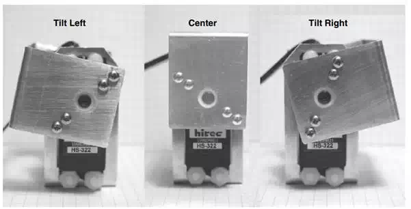
Servomotor bracket travel
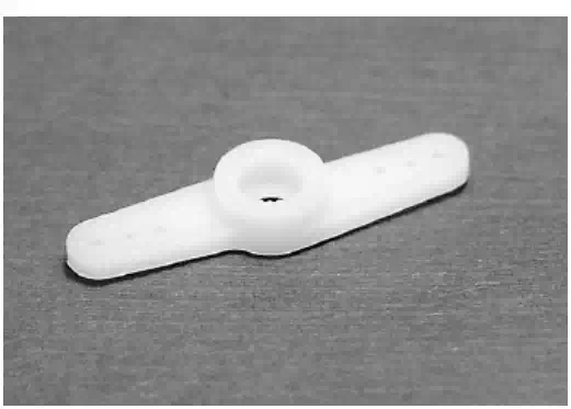
HI Tec servomotor horn.
bracket with servomotor horn attached.
To place the servomotor secure in bracket A into its mating part bracket B, slip the end of the bindingheld post through the hole in the mating part. Next slip the servomotor’s spindle into the horn. Finished assembly.
Side view of placing servomotor in A bracket.
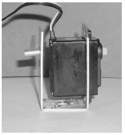
A bracket with servomotor
attached with plastic screws and nuts.
Hi Tec servomotor horn.
B bracket with servomotor horn attached.