Actuators and Drive Systems
Actuators are one of the key components contained in a robotic system. A robot has many degrees of freedom, each of which is a servoed joint generating desired motion. We begin with basic actuator characteristics and drive amplifiers to understand behavior of servoed joints.
Most of today’s robotic systems are powered by electric servomotors. Therefore, we focus on electromechanical actuators.
DC Motors
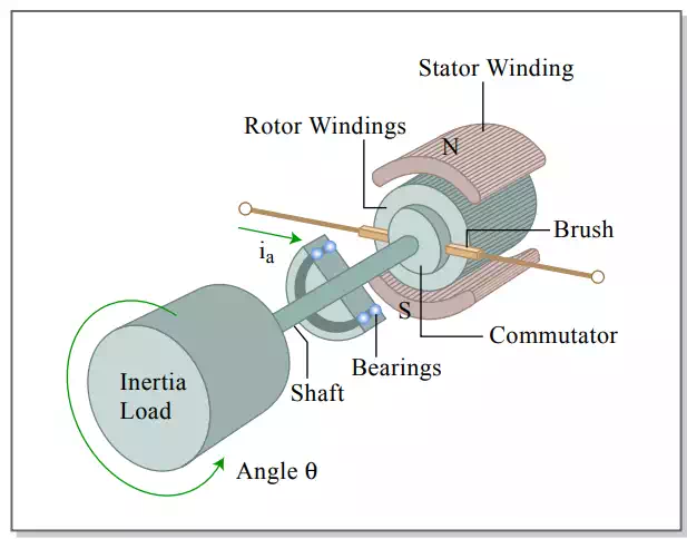
Illustrates the construction of a DC servomotor, consisting of a stator, a rotor, and a commutation mechanism. The stator consists of permanent magnets, creating a magnetic field in the air gap between the rotor and the stator. The rotor has several windings arranged symmetrically around the motor shaft. An electric current applied to the motor is delivered to individual windings through the brush-commutation mechanism, as shown in the figure. As the rotor rotates the polarity of the current flowing to the individual windings is altered. This allows the rotor to rotate continually.
Construction of DC motor
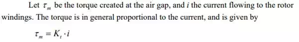
where the proportionality constant is called the torque constant, one of the key parameters describing the characteristics of a DC motor. The torque constant is determined by the strength of the magnetic field, the number of turns of the windings, the effective area of the air gap, the radius of the rotor, and other parameters associated with materials properties.
In an attempt to derive other characteristics of a DC motor, let us first consider an idealized energy transducer having no power loss in converting electric power into mechanical power. Let E be the voltage applied to the idealized transducer. The electric power is then given by E ⋅i , which must be equivalent to the mechanical power:
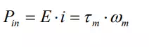
where ω m is the angular velocity of the motor rotor. Substituting eq.(1) into eq.(2) and dividing both sides by i yield the second fundamental relationship of a DC motor:

The above expression dictates that the voltage across the idealized power transducer is proportional to the angular velocity and that the proportionality constant is the same as the torque constant given by eq.(1). This voltage E is called the back emf (electro-motive force) generated at the air gap, and the proportionality constant is often called the back emf constant.
Note that, based on eq.(1), the unit of the torque constant is Nm/A in the metric system, whereas the one of the back emf constant is V/rad/s based on eq.(2).
Show that the two units, Nm/A and V/rad/s, are identical.
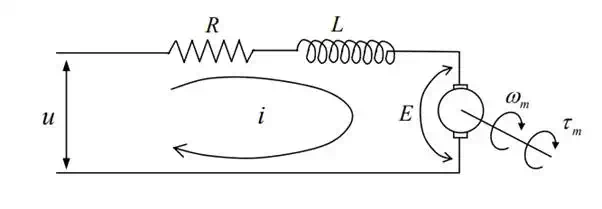
The actual DC motor is not a loss-less transducer, having resistance at the rotor windings and the commutation mechanism. Furthermore, windings may exhibit some inductance, which stores energy. the schematic of the electric circuit, including the windings resistance R and inductance L.
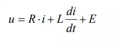
where u is the voltage applied to the armature of the motor
Electric circuit of armature
we can obtain the actual relationship among the applied voltage u, the rotor angular velocity ω m , and the motor torque τm .
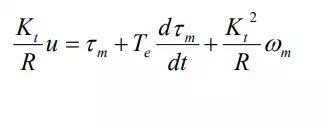
This is called the torque-speed characteristic. Note that the motor torque increases in proportion to the applied voltage, but the net torque reduces as the angular velocity increases.
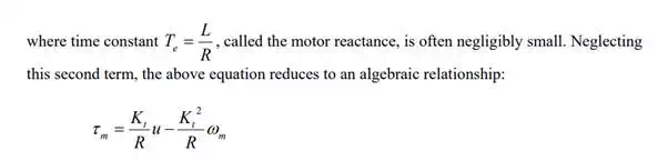
illustrates the torque-speed characteristics. The negative slope of the straight lines, Kt 2 / R− , implies that the voltage-controlled DC motor has an inherent damping in its mechanical behavior.
The power dissipated in the DC motor is given by
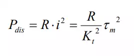
Taking the square root of both sides yields

where the parameter is called the motor constant. The motor constant represents how effectively electric power is converted to torque. The larger the motor constant becomes, the larger the output torque is generated with less power dissipation. A DC motor with more powerful magnets, thicker winding wires, and a larger rotor diameter has a larger motor constant. A motor with a larger motor constant, however, has a larger damping, as the negative slope of the torque speed characteristics becomes steeper, as illustrated.
Torque-speed characteristics and output power

Taking into account the internal power dissipation, the net output power of the DC motor is given by
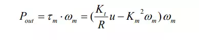
This net output power is a parabolic function of the angular velocity, as illustrated in Figure 2.1.3. It should be noted that the net output power becomes maximum in the middle point of the velocity axis, i.e. 50 % of the maximum angular velocity for a given armature voltage u. This implies that the motor is operated most effectively at 50 % of the maximum speed. As the speed departs from this middle point, the net output power decreases, and it vanishes at the zero speed as well as at the maximum speed. Therefore, it is important to select the motor and gearing combination so that the maximum of power transfer be achieved.