How the circuit works
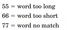
Before we can get into the nuts and bolts of how the interface circuit functions, we must look at the binary information output by the speech recognition circuit. The output of the speech recognition circuit consists of two 4bit binarycoded decimal (BCD) numbers. This binary (BCD) information is shown on the speech circuit’s two-digit digital display. Whenever a word is detected, the circuit uses the digital display to output the word number it has recognized, or else it outputs its unrecognized/error code. If the word detected is not recognized, the circuit will display one of the following error codes:
Our interface design incorporates a PIC microcontroller. A preprogrammed microcontroller’s (16F84) first job is to determine if a word has been spoken. To do this, we use an LM339 comparator. A reference voltage for the comparator is generated using a voltage divider made up of
Speech recognition interface (active high outputs) SRI03.
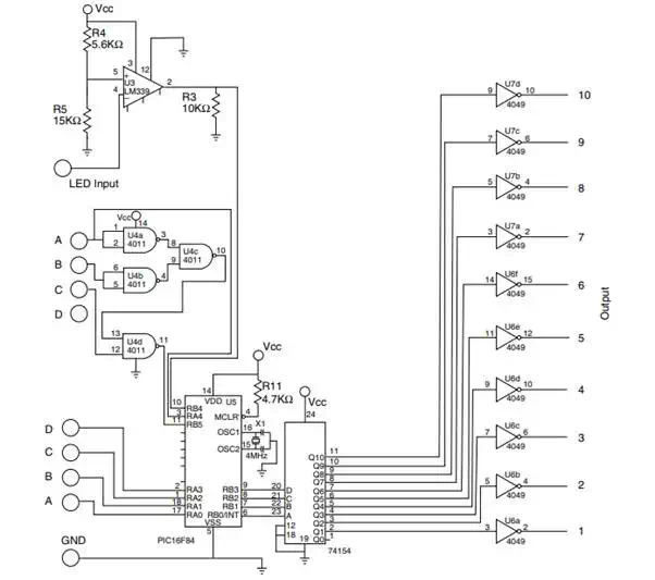
resistors R4 and R5. The reference voltage is placed on pin 5 of the comparator. Pin 4 of the comparator is connected to the LED lead on the speech recognition circuit. Whenever a word is detected, the LED blinks off momentarily. The output of the comparator (pin 2) is connected to pin 10 (RB4) of the 16F84 microcontroller. The output of the comparator (pin 2) is usually high (�5 V). When a word is detected, the output (pin 2) drops to ground momentarily. The microcontroller monitors this line to determine when a word has been detected.
Once a word has been detected, it is necessary for the interface to read the BCD output from the speech recognition circuit. By using the high and low digit BCD nibbles, it’s possible to distinguish trained target words. To do so, the interface must distinguish the error codes 55, 66, and 77 from trained words numbered 5, 6, and 7. To accomplish this, the interface circuit uses four NAND gates off the 4011 integrated circuit. The NAND gates are connected to the high digit nibble. If the high digit BCD nibble has the equivalent word numbers of 5, 6, or 7, the output from the four NAND gates is low. The output from the four NAND gates is connected to pin 11 (RB5) of the 16F84. The 16F84 reads this pin to determine if the highdigit nibble is a 5, 6, or 7 (0 V or ground). If these numbers are not displayed, the output of the NAND gates is high (�5 V).
So far our circuit can tell when a word has been detected and if the resulting word is an error code. If the output of the speech recognition circuit is an error code, nothing else happens; the microcontroller loops back to the beginning of the program, waiting for another word detection. On the other hand, if a word is detected and it is not an error code, the microcontroller passes the lowdigit number through to the 74HC154 (4 to 16line decoder) IC. The 74HCT154 decoder reads the binary number passed to it and brings the corresponding pin equivalent to that number low.
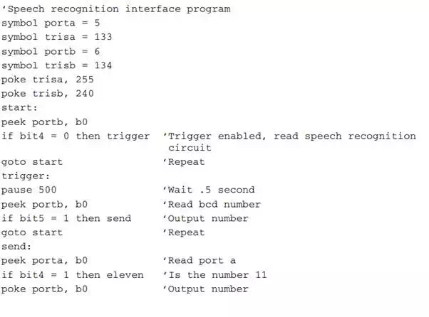
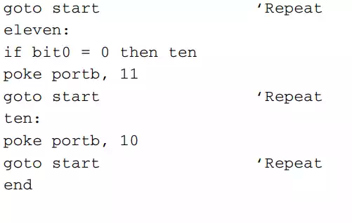
PIC 16F84 microcontroller program
The PIC 16F84 used in both interface circuits contains the following Pic Basic program:
Active high output
The outputs from the 74HCT154 each pass through a 4049 inverting buffer to supply a 15Vdc active high output signal.
SPDT relay output
The front end of the circuit is identical. The changes are seen in the back end of the circuit. The active low output signals from the 74HCT154 each connect to one of the 10 PNP transistors, each of which controls a corresponding relay. Each relay has a normally open (N.O.) switch and normally closed (N.C.) switch. The relay switches are rated at 124 V ac at 0.5 A or 24 V dc at 1 A. The relay itself consumes approximately 30 mA of current when it is turned on.