Speech Recognition Circuit
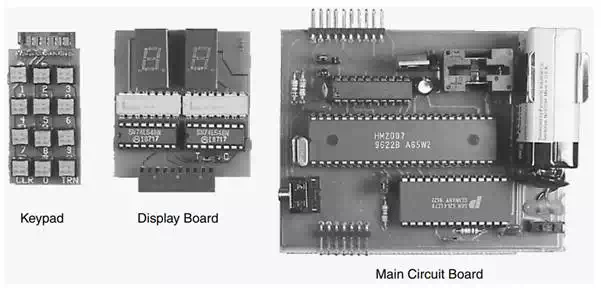
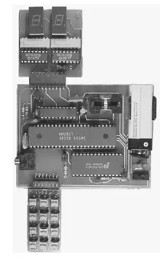
The speech recognition circuit is available as a kit from Images SI Inc. You can purchase the main components, HM2007, SRAM, and printed circuit boards separately if you like and build from scratch. The kit takes a modular approach and uses three separate printed circuit (PC) boards. The three PC boards are the main circuit board containing the speech recognition circuit, digital display board, and keypad. The keypad and digital display are removable from the main circuit board. They are needed to communicate with and program the main speech recognition circuit. After the programming is accomplished, the digital display and keyboard can be removed, and the main circuit embedded into another circuit to add speech control.
Circuit construction
The schematic You can hardwire this circuit to a breadboard if you like. I would recommend purchasing the three PCB boards that are available for this project; see Parts List. When you use the PC board, the components are mounted on the top silkscreen side of the board. Begin construction by soldering the IC sockets onto the PC boards. Next mount and solder all the resistors. Now mount and solder the 3.57MHz crystal and red LED. The long lead of the LED is positive. Next solder the capacitors and 7805 voltage regulators. Solder the seven position headers on the keypad to the main circuit board. Next solder the 10 position headers on the display board and main circuit board.
Three modular circuit boards.
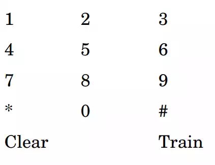
Keypad
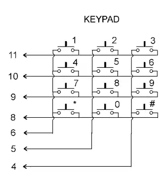
The keypad is made up of 12 normally open (N.O.) pushbutton switches
To train
To train the circuit, first attach the keypad and digital display to the main circuit board . Next select your word length. Place a jumper on the two pin WD header on the main circuit board to select a 20words vocabulary, each with a 2s word length. Leave the jumper off to select a 40words vocabulary, each with a 1s word length. Plug in the headset microphone. When power is applied, the HM2007 checks the static RAM, outputs “00” on the digital display, and lights the red LED (READY). The circuit is in the ready mode. In the ready mode the circuit is listening for a verbal command or waiting to be trained.
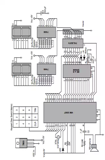
Schematic of speech recognition circuit
Keypad wiring
Modular components put together for training.
To train the circuit, begin by pressing the word number you want to train on the keypad. In this exercise I am assuming you choose the 20words vocabulary. In this mode the circuit can be trained to recognize up to 20 words. Use any numbers between 1 and 20. For example, press the number 1 to train word number 1. When you press the number(s) on the keypad, the red LED will turn off. The number pressed on the keypad is shown on the digital display. Next press the # key for train. When the # key is pressed, it signals the chip to listen for a training word, and the red LED turns back on. Now speak the word you want the circuit to recognize into the headphone microphone clearly. The LED should blink off momentarily; this is a signal that the word has been accepted.
Continue training new words in the circuit, using the procedure outlined above. Press the 2 key, then the # key to train the second word, and so on. The circuit will accept up to either 20 or 40 words, depending on the lengths of the words. You do not have to enter 20 words into memory to use the circuit. If you want, you can use as few word spaces as you require. The procedure for training 40 words is identical, except that you can choose word numbers between 1 and 40.
Testing Recognition
The circuit is continually listening. Repeat a trained word into the microphone. The number of the word should be displayed on the digital display. For instance, if the word directory was trained as word number 5, then saying the word directory into the microphone will cause the number 5 to be displayed.
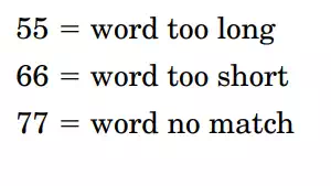
Error codes
The chip provides the following error codes.
Clearing the trained word memory
To erase all the words in the SRAM memory (training), press 99 on the keypad and then press the * key. The display will scroll through the numbers 1 through 20 (or 1 through 40 if in 1s word length mode) quickly, clearing out the memory.
To erase a single word space, press the number of the word you want to clear and then press the * key
Independent Recognition System
In addition to speech commands, this circuit allows you to experiment with other facets of speech recognition technology. For instance, you can experiment with speaker independent systems. This system is inherently speaker dependent, meaning that the voice that trained the circuit also uses it. To experiment with speaker independent recognition (multiuser), try the following technique. Set the WD jumper on the main circuit board to the 40words vocabulary with a 0.96s word length. Now we will use four word spaces for each command word. We will arrange the words so that the command words will be recognized by just decoding the least significant digit (number) on the digital display.
This is accomplished by allocating the word spaces 01, 11, 21, and 31 to the first target or command word. When the circuit is in recognition mode, we only decode the least significant digit number, in this case X1 (where X is any number from 0 to 3) to recognize the target word.
We do this for the remaining word spaces. For instance, the second target word will use word spaces 02, 12, 22, and 32. We continue in this manner until all the words are programmed.
If possible, use a different person to speak the word. This will enable the system to recognize different voices, inflections, and enunciations of the target word. The more system resources that are allocated for independent recognition, the more robust the circuit will become.
There are certain caveats to be aware of. First you are trading off word vocabulary number for speaker independence. The effective vocabulary drops from 40 words to 10 words.
The speech interface control circuit shown later may be used in this speaker independent experimental capacity.
Voice Security System
This HM2007 wasn’t designed for use in a voice security system. But this doesn’t prevent you from experimenting with it for that purpose. You may want to use three or four keywords that must be spoken and recognized in sequence in order to activate a circuit that opens a lock or allows entry.