Braitenberg Vehicles
In 1984 Valentino Braitenberg published a book titled Vehicles—Experiments in Synthetic Psychology. In his book Valentino describes a number of wondrous vehicles that exhibit interesting behaviors based on the use of a few electronic neurons
Similar in concept to Walter’s seminal neural work with his robot tortoises, Valentino’s vehicle behavior is more straightforward, making it somewhat easier to follow both theoretically and logically. This also makes it easier to implement his ideas into real designs for robots.
In this chapter we will build a few Braitenberg type vehicles. At the heart of Braitenberg vehicles is his description of a basic vehicle, which is a sensor connected to a motor. Braitenberg continues to explain the relationship between the sensor and motor. The relationship is essentially the connection between the sensor and motor, and this connection ought to be considered as a neuron. With the connection configured as a neuron, the structure is Instead of a vehicle we will describe the structure diagram as a small neural network.
At the front end of the network we find a sensor, followed by the neuron and finally the output motor. The sensor detects the intensity of light and outputs a proportional signal to the motor. High intensity light produces high rpm’s (revolutions per minute) from the motor. Low intensity light produces slow rpm’s
Consider the sensor portion as modular and interchangeable. Other sensors can be plugged in and incorporated to detect any number of environmental variables, for example, heat, pressure, sound, vibration, magnetic fields (compass), electrical fields, radioactivity, and gases (toxic or otherwise). In addition, the motor, like the sensor, represents a singular example of an output module. Other output modules could include a second neuron (or neural layer), electric circuit, on/off switch, light source, etc.
Basic neuron setup, sensor input, neuron, and motor output.
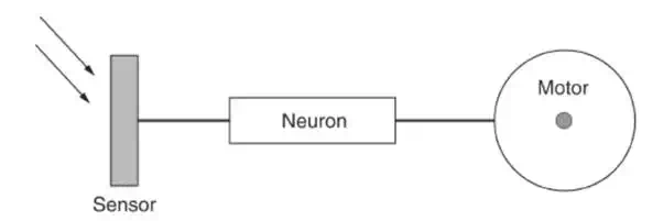
The neuron’s input is the output of the sensor, and the neuron’s output activates a motor in relationship to its input. The input/output “relationship” of the neuron can be made to be one of many different mathematical functions. The relationship may also be called connection strength or connection function when you are reading the neural network literature. The relationship is one of the most important variables we can modify when programming our robot.
Neural I/O Relationships
When the neuron is stimulated, it generates an output. As stated, there are a number of mathematical functions that can exist inside the neuron. These functions act upon the neuron’s input (sensor output) and pass through the results to the neuron’s output. Let’s examine a few of them
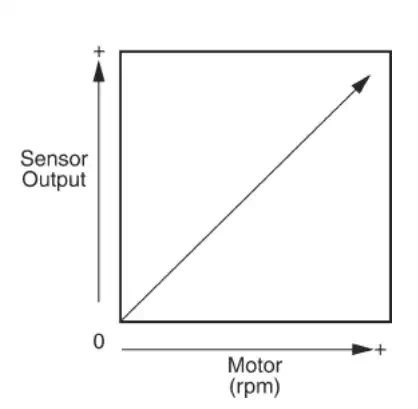
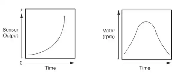
· Positive proportional. As input from the sensor increases, activation (rpm’s) of the motor increases in proportion
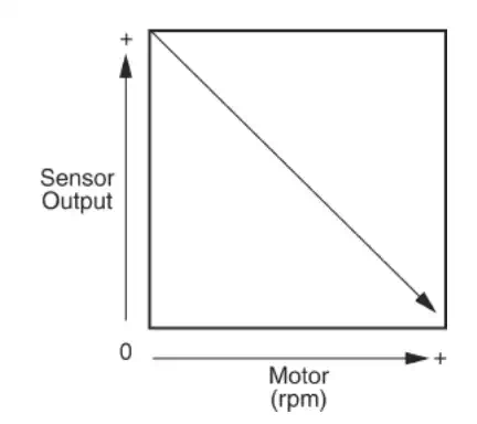
· Negative proportional. As input from the sensor increases, activation (rpm’s) of the motor decreases in proportion
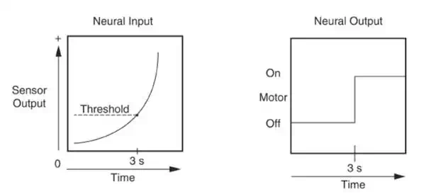
· Digital. As input from the sensor output exceeds a predetermined (programmed) threshold (that may be positive or negative), the motor is activated
· Gaussian. As input from the sensor increases, output passes through a gaussian function for motor activation
Essentially the neuron may incorporate any mathematical function. It would perform this function on the sensory input to generate an appropriate output. I have provided an example of only a few of the more common functions available
Vehicles
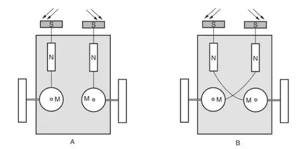
Using the basic neural setup, we can construct a few simple vehicles that exhibit interesting behaviors. Figure 9.6 illustrates two vehicles labeled A and B. Both vehicles use the positive proportional neural setup with a light intensity sensor.
Graph of positive proportional transfer function. As sensor output increases, motor output increases.
Graph of negative proportional transfer function. As sensor output increases, motor output decreases.
Graph of digital transfer function. As sensor output increases, output remains unchanged until threshold is reached, then output switches full on.
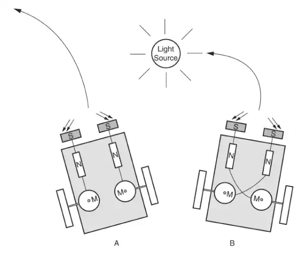
Vehicle A, if both sensors are evenly illuminated by a light source, will speed up and, if possible, run into the light source. However, if the light source is off to one side, the sensor on the side of the light source will speed a little faster than the sensor/motor on other side. This will cause the vehicle to veer away from the light source
Vehicle B, if both sensors are evenly illuminated by a light source, will speed up and, if possible, run into the light source (same as vehicle A). If the light source is off to one side, vehicle B will turn toward the light source
Graph of gaussian function. As sensor output increases, output follows a gaussian curve.
Wiring of two Braitenberg vehicles labeled A and B.
Building Vehicles
It’s time to put the theory to the test and see if it works. Let’s assemble the materials needed to build a vehicle. The photovore’s basic operating procedure is like Walter’s robot. It tracks and follows a light source. The base of the vehicle is a sheet of aluminum 8 in long by 4 in wide by 1 �8 in thick. We will use two gearbox motors for propulsion and steering and one multidirectional front wheel.
We will try a new construction method with this robot. Instead of securing the gearbox motors with machine screws and nuts, we will use 3M’s industrial brand double sided tape. This double sided tape, once cured, is as strong as pop rivets. I tried to separate a sample provided by 3M. It consisted of two flat pieces of metal secured with the tape. Even when I used pliers, it was impossible. 3M states that the tape requires 24 h to reach full strength. You may not achieve the fullstrength capability of the tape unless you follow the 3M procedure.
Function of A and B Braitenberg vehicles
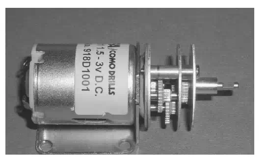
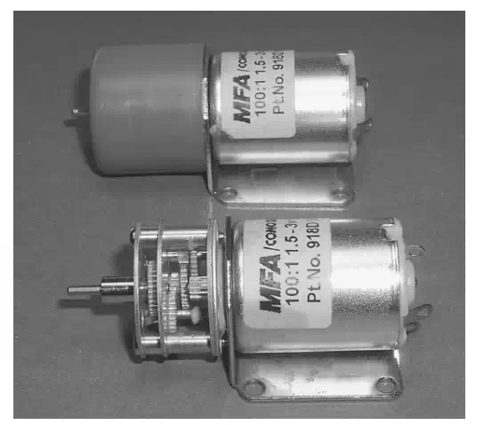
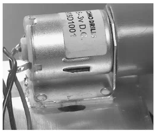
The gearbox motor is a 918D type (see Fig. 9.8). The gearbox motor at the top of the picture has an orange cowl that is covering the gears. Notice the flat mounting bracket that is perfect for securing to the vehicle base. The doublesided tape is cut lengthwise to fit the base of bracket to the gearbox motor. The exposed side of the tape is immediately secured to the gearbox motor bracket. Then the motor is positioned on the bottom of the vehicle base, the protective covering of the tape is removed, and the gearbox motor is firmly placed onto the bottom of the vehicle base The second gearbox motor is secured to the other side in a similar manner.
Back wheels
The shaft diameter of the gearbox motor is a little too small to make a good friction fit to the rubber wheel. To beef up the diameter, cut a small 1 to 1.5 in length of the 3mm tubing; see Parts List. Place the tubing over the gearbox motor shaft, and collapse the tubing onto the shaft, using pliers. There is a small cutaway on the gearbox motor shaft (see Fig. 9.10). If you can collapse the tubing into this cutaway, you will create a strong fit between the shaft and the tubing that will not pull off easily .
The tubing adds to the diameter of the shaft and will make a good friction fit with the rubber wheels. Simply push the center holes of the wheels onto the tubing/shaft, and you are finished.
A 918D 100:1 Gearbox motor.
3M double sided tape is used to secure gearbox motor to base of vehicle.
Gearbox motor showing cutaway on output shaft