Architecture of Hybrid Position/Force Control System
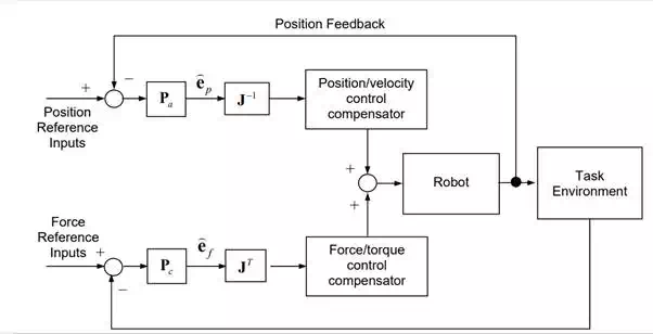
Based on Mason’s Principle, a hybrid position/force control system can be constructed in such a way that the robot control system may not have a conflict with the natural constraints of the task process, while performing the task towards the task goal. Figure 9.1.5 shows the block diagram of a hybrid position/force control system. The upper half of the diagram is position control loops, where artificial kinematic constraints are provided as reference inputs to the system and are compared with the actual position of the end-effecter. The lower half of the diagram is force control loops, where artificial static constraints are provided as reference inputs to the feedback loops and are compared with the actual force and moment at the end-effecter. Note that feedback signals are described in an appropriate C-frame attached to the end-effecter.
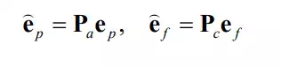
If the feedback signals are noise-less and the C-frame is perfectly aligned with the actual task process, the position signal of the feedback loop must lie in the admissible motion space, and the force being fed back must lie in the constraint space. However, the feedback signals are in general corrupted with sensor noise and the C-frame may be misaligned. Therefore, the position signal may contain some component in the constraint space, and some fraction of the force signal may be in the admissible motion space. These components are contradicting with the natural constraints, and therefore should not be fed back to the individual position and force controls. To filter out the contradicting components, the feedback errors are projected to their own subspaces, i.e. the positional error ep mapped to the admissible motion space Va and the force feedback error ef mapped to the constraint space Vc. In the block diagram these filters are shown by projection matrices, Pa and Pc :
When the C-frame axes are aligned with the directions of the individual position and force control loops, the projection matrices are diagonal, consisting of only 1 and 0 in the diagonal components. In the case of the peg-in-the-hole problem, they are:
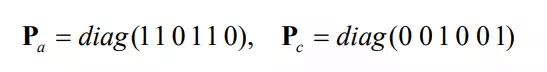
In case of Example 9.2 where the C-frame axes are not the directions of the individual position and force control loops, the projection matrices are not diagonal.
Block diagram of hybrid position/force control system
These feedback errors, p f e e and , are in the C-frame, hence they must be converted to the joint space in order to generate control commands to the actuators. Assuming that the positional error vector is small and that the robot is not at a singular configuration, the position feedback error in joint coordinates is given by
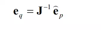
where J is the Jacobian relating the end-effecter velocities in the C-frame to joint velocites. The force feedback error in the joint coordinates, on the other hand, is obtained based on the duality principle:
These two error signals in the joint coordinates are combined after going through dynamic compensation in the individual joint controls.