Statics
Robots physically interact with the environment through mechanical contacts. Mating work pieces in a robotic assembly line, manipulating an object with a multi-fingered hand, and negotiating a rough terrain through leg locomotion are just a few examples of mechanical interactions. All of these tasks entail control of the contacts and interference between the robot and the environment. Force and moment acting between the robot end-effecter and the environment must be accommodated for in order to control the interactions. In this chapter we will analyze the force and moment that act on the robot when it is at rest.
A robot generates a force and a moment at its end-effecter by controlling individual actuators. To generate a desired force and moment, the torques of the multiple actuators must be coordinated. As seen in the previous chapter, the sensitivities of the individual actuators upon the end-effecter motion, i.e. the Jacobian matrix, are essential in relating the actuator (joint) torques to the force and moment at the end-effecter. We will obtain a fundamental theorem for force and moment acting on a multi degree-of-freedom robot, which we will find is analogous to the differential kinematics discussed previously.
Free Body Diagram
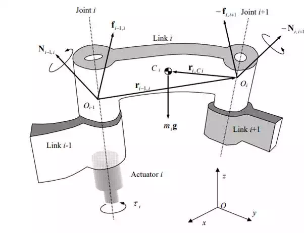
We begin by considering the free body diagram of an individual link involved in an open kinematic chain. Figure 6.1.1 shows the forces and moments acting on link i, which is connected to link i-1 and link i+1 by joints i and i+1, respectively. Let Oi be a point fixed to link i located on the joint axis i+1 and Oi-1 be a point fixed to link i-1 on the joint axis i. Through the connections with the adjacent links, link i receives forces and moments from both sides of the link. Let fi-1,i be a three-dimensional vector representing the linear force acting from link i-1 to link i. Likewise let fi,i+1 be the force from link i to link i+1. The force applied to link i from link i+1 is then given by –fi,i+1. The gravity force acting at the mass centroid Ci is denoted mig, where mi is the mass of link i and g is the 3x1 vector representing the acceleration of gravity. The balance of linear forces is then given by

Note that all the vectors are defined with respect to the base coordinate system O-xyz.
Next we derive the balance of moments. The moment applied to link i by link i-1 is denoted Ni-1,i, and therefore the moment applied to link i by link i+1 is –Ni,i+1. Furthermore, the linear forces fi-1,i and –fi,i+1 also cause moments about the centroid Ci. The balance of moments with respect to the centroid Ci is thus given by

where ri-1,i is the 3x1 position vector from point Oi-1 to point Oi with reference to the base coordinate frame, and ri,Ci represents the position vector from point Oi to the centroid Ci.
Free body diagram of the i-th link

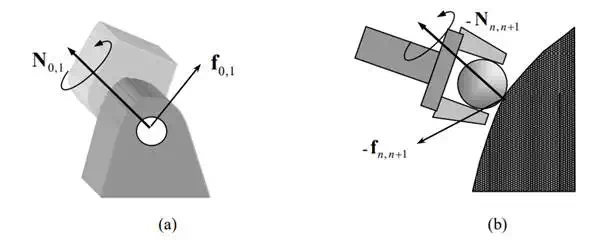
The force i−1, i f and moment i−1,i are called the coupling force and moment between the adjacent links i and i-1. For i=1, the coupling force and moment are 0,1 and 0,1 . These are interpreted as the reaction force and moment applied to the base link to which the arm mechanism is fixed. See Figure 6.1.2-(a). When i = n, on the other hand, the above coupling force and moment become n, n+1 and n, n+1 . As the end-effecter, i.e. link n, contacts the environment, the reaction force acts on the end-effecter. See Figure 6.1.2-(b). For convenience, we regard the environment as an additional link, numbered n+1, and represent the reaction force and moment by - and - , respectively.
Force and moment that the base link exerts on link 1 (a), and the ones that the environment exerts on the end-effecter, the final link (b)

The above equations can be derived for all the link members except for the base link, i.e. i=1,2, …, n. This allows us to form 2n simultaneous equations of 3x1 vectors. The number of coupling forces and moments involved is 2(n+1). Therefore two of the coupling forces and moments must be specified; otherwise the equations cannot be solved. The final coupling force and moment, n, n+1 f and n, n+1 , are the force and moment that the end-effecter applies to the environment. It is this pair of force and moment that the robot needs to accommodate in order to perform a given task. Thus, we specify this pair of coupling force and moment, and solve the simultaneous equations. For convenience we combine the force and the moment , to define the following six-dimensional vector:

We call the vector F the endpoint force and moment vector, or the endpoint force for short.
Energy Method and Equivalent Joint Torques
In this section we will obtain the functional relationship between the joint torques and the endpoint force, which will be needed for accommodating interactions between the end-effecter and the environment. Such a functional relationship may be obtained by solving the simultaneous equations derived from the free body diagram. However, we will use a different methodology, which will give an explicit formula relating the joint torques to the endpoint force without solving the simultaneous equations. The methodology we will use is the energy method, sometimes referred to as the indirect method. Since the simultaneous equations based on the balance of forces and moments are complex and difficult to solve, we will find that the energy method is the ideal choice when dealing with complex robotic systems.
In the energy method, we describe a system with respect to energy and work. Therefore, terms associated with forces and moments that do not produce, store, or dissipate energy are eliminated in its basic formula. In the free body diagram shown in Figure 6.1.1, many components of the forces and moments are so called “constraint forces and moments” merely joining adjacent links together. Therefore, constraint forces and moments do not participate in energy formulation. This significantly reduces the number of terms and, more importantly, will provide an explicit formula relating the joint torques to the endpoint force.
To apply the energy method, two preliminary formulations must be performed. One is to separate the net force or moment generating energy from the constraint forces and moments irrelevant to energy. Second, we need to find independent displacement variables that are geometrically admissible satisfying kinematic relations among the links.
The actuator torques and the coupling forces and moments acting at adjacent joints. The coupling force i−1, i f and moment Ni−1,i are the resultant force and moment acting on the individual joint, comprising the constraint force and moment as well as the torque generated by the actuator. Let bi-1 be the 3x1 unit vector pointing in the direction of joint axis i, as shown in the figure. If the i-th joint is a revolute joint, the actuator generates joint torque i τ about the joint axis. Therefore, the joint torque generated by the actuator is one component of the coupling moment along the direction of the joint axis:

For a prismatic joint, such as the (i+1)-st joint illustrated in Figure 6.2.1, the actuator generates a linear force in the direction of the joint axis. Therefore, it is the component of the linear coupling force projected onto the joint axis.

Note that, although we use the same notation as that of a revolute joint, the scalar quantity i τ has the unit of a linear force for a prismatic joint. To unify the notation we use i τ for both types of joints, and call it a joint torque regardless the type of joint.
Joint torques as components of coupling force and moment

We combine all the joint torques from joint 1 through joint n to define the nx1 joint torque vector:

The joint torque vector collectively represents all the actuators’ torque inputs to the linkage system. Note that all the other components of the coupling force and moment are borne by the mechanical structure of the joint. Therefore, the constraint forces and moments irrelevant to energy formula have been separated from the net energy inputs to the linkage system.
In the free body diagram, the individual links are disjointed, leaving constraint forces and moments at both sides of the link. The freed links are allowed to move in any direction. In the energy formulation, we describe the link motion using independent variables alone. Remember that in a serial link open kinematic chain joint coordinates ( q " q) T q = 1 n are a complete and independent set of generalized coordinates that uniquely locate the linkage system with independent variables. Therefore, these variables conform to the geometric and kinematic constraints. We use these joint coordinates in the energy-based formulation.
The explicit relationship between the n joint torques and the endpoint force F is given by the following theorem:
Theorem
Consider an n degree-of-freedom, serial link robot having no friction at the joints. The joint torques that are required for bearing an arbitrary endpoint force are given by

where J is the 6 x n Jacobian matrix relating infinitesimal joint displacements dq to infinitesimal end-effecter displacements dp:

Note that the joint torques in the above expression do not account for gravity and friction. They are the net torques that balances the endpoint force and moment. We call of eq.(3) the equivalent joint torques associated with the endpoint force F.
Proof
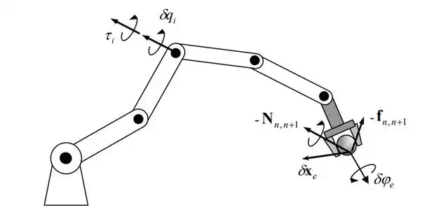
We prove the theorem by using the Principle of Virtual Work. Consider virtual displacements at individual joints, 1 n , and at the end-effecter, T e T e , as shown in Figure 6.2.2. Virtual displacements are arbitrary infinitesimal displacements of a mechanical system that conform to the geometric constraints of the system. Virtual displacements are different from actual displacements, in that they must only satisfy geometric constraints and do not have to meet other laws of motion. To distinguish the virtual displacements from the actual displacements, we use the Greek letter δ rather than the roman d.
Virtual displacements of the end effecter and individual joints

We assume that joint torques 1 2 n and endpoint force and moment, -F, act on the serial linkage system, while the joints and the end-effecter are moved in the directions geometrically admissible. Then, the virtual work done by the forces and moments is given by

According to the principle of virtual work, the linkage system is in equilibrium if, and only if, the virtual work δWork vanishes for arbitrary virtual displacements that conform to geometric constraints. Note that the virtual displacements δq and δp are not independent, but are related by the Jacobian matrix given in eq.(5). The kinematic structure of the robot mechanism dictates that the virtual displacements δp is completely dependent upon the virtual displacement of the joints, δq. Substituting eq.(5) into eq.(6) yields

Note that the vector of the virtual displacements δq consists of all independent variables, since the joint coordinates of an open kinematic chain are generalized coordinates that are complete and independent. Therefore, for the above virtual work to vanish for arbitrary virtual displacements we must have

the theorem has been proven.
The above theorem has broad applications in robot mechanics, design, and control. We will use it repeatedly in the following chapters.
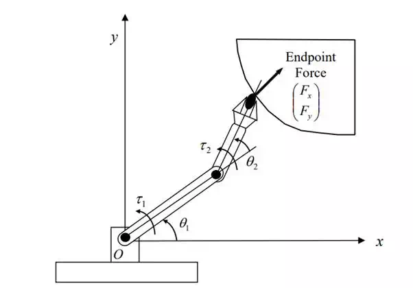
A two-dof articulated robot having the same link dimensions as the previous examples. The robot is interacting with the environment surface in a horizontal plane. Obtain the equivalent joint torques T 1 needed for pushing the surface with an endpoint force of T . Assume no friction.

The Jacobian matrix relating the end-effecter coordinates e and to the joint displacements x e y θ1 and θ 2 has been obtained in the previous chapter:
the equivalent joint torques are obtained by simply taking the transpose of the Jacobian matrix.

Two-dof articulated robot pushing the environment surface
