Defining work space area
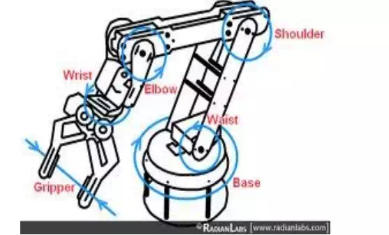
There are two types of work space area: parallel work space and perpendicular work space. It is very important to determine work space area and to know the planes of work space. In the picture 6.14 the robot of five degrees of freedom as we can see there are several rotations with two work spaces. First Base and wrest they rotate in parallel work space. Then waist, shoulder and elbow they are rotating in parallel work space to each other. Then base and wrest they rotate in perpendicular work space against waist, shoulder and elbow.
Spatial manipulator: that has more planes to move through with more perpendicular and parallel axes to each other like industrial robot as an example in figure.
Example with spatial robot
Notice: This example is called 5RP manipulator; all these axes are moved with series of cables and pulleys which are connected to the drive motor.
Manipulator task is to position an object and to define how many orientations are possible for a specific position. This issue is required for mechanical engineers to answer. By adding more degree of freedom you can add more orientations and ranges of orientation, but control problem gets bigger. Notice number of possible orientations (directions) depends on the position of the object.
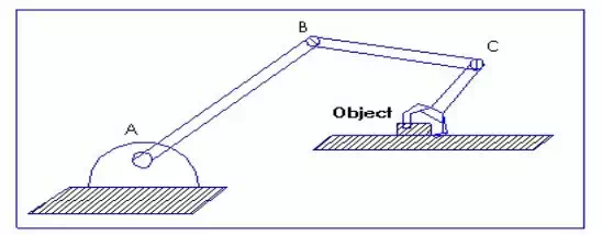
Example of positioning an object
In the following picture we have just one orientation
one orientation example
Work space:
we notice from the following picture 6.17 that if B rotates, then work space will be as we see in the picture but if we assume that L1 = L2 then C1 will touch the base A and we notice that we have a bigger workspace (Craig 2005, 102-103.)
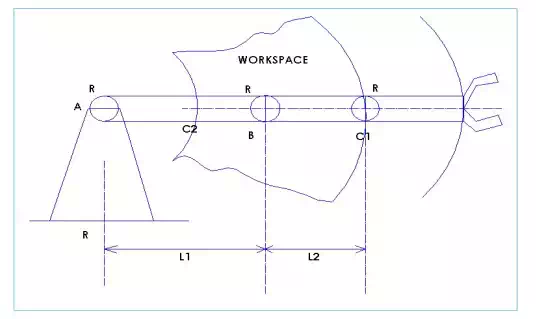
Example to show a work space
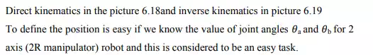
Direct kinematics 2R Inverse kinematics 2R
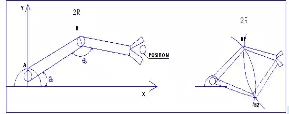
There are 3 axis or 3R manipulator robot in pictures. There is The Inverse kinematics in picture and direct kinematics (Craig 2005, 103- 104.). Notice is the orientation angle.
Direct kinematics 3R Inverse kinematics 3R
How to define the inverse kinematics in 2R manipulator
When the base position, end effector position and the linkage length are given, then we have unique solution by drawing two circles. The centre of these circles is: the position of the base A and the position of the end effector. Then we take the 2 cross point which represents direct kinematics and inverse kinematics solutions.
How to define the inverse kinematics in 3R manipulator
When end effector position and the linkage length are given, then we have unique solution by drawing two circles and the centre of these circles is: The position of the base A and the position of C. Notice that the position of C stays the same. (Craig 2005, 102-105.)