How to Expand the Workspace of Parallel Robots
The parallel robot has excellent characteristics such as high speed, high precision, and high rigidity. However, mechanical collisions between limbs and complexly existing singular configurations restrict its workspace. In this chapter, firstly, methods for expanding the translational workspace of the parallel robot are discussed. The parallel robot has multiple solutions of the inverse and forward displacement analysis. By changing its configurations from one solution to another, the parallel robot can expand its translational workspace. However, conventional nonredundant parallel robot encounters singularity during the mode change. Singularity-free mode changes of the parallel robot by redundant actuation are introduced. Next, methods for expanding the rotational workspace of the parallel robot are shown. In order to achieve the large rotation, some mechanical gimmicks by gears, pulleys, and helical joints have been embedded in the moving part. A novel differential screw-nut mechanism for expanding the rotational workspace of the parallel robot is introduced.
Expanding the translational workspace
MODE CHANGE OF THE PARALLEL ROBOT
Schematic model of a planar two-dof (degree-of-freedom) serial robot and a planar two-dof parallel robot is illustrated in Figures 1 and 2, respectively. R and P represent the rotational pair and prismatic (sliding) pair, respectively. Underline indicates that an actuator is located at the pair, namely, R and Prepresent active rotational pair and active prismatic pair, and R and P represent passive ones. The serial robot in Figure 1 is represented as RR mechanism, and the parallel robot in Figure 2 is represented as 2PRR mechanism. In 2PRR, “2” means that the two PRR mechanisms are connected to the output link (end effector or hand) in parallel. In order to control the position of the hand, forward displacement analysis gives the position and orientation of the hand from the displacements of the active pairs (joints), and inverse displacement analysis gives the displacements of the active joints from the position and orientation of the hand. As shown in Figures 1 and 2(a), different solutions for inverse displacement analysis and different position of the joints for a position and orientation of the hand exist. In the robotics, the solution of the inverse displacement analysis is called as the working mode. Changing the positions of the joints between the different working modes, at that time the robot changes its configuration, is named as the working mode change. In the case of the serial robot, there exists only one solution for the forward displacement analysis; namely, when the displacement of the active joints is given, the position and orientation of the robot are fixed. However, in the case of the parallel robot, there exist different solutions for the forward displacement analysis as shown in Figure 2(b). The solution of the forward displacement analysis is named as the assembly mode. Parallel robot can change the position and orientation of the hand with the same displacements of the actuated joints. Note here that the parallel robot in Figure 2 is designed as free of the mechanical interferences such as limb collisions. Parallel robot can expand the workspace of the hand by the assembly mode change as shown in Figure 2(b).

FIGURE 1.
Working mode change of RR serial robot.
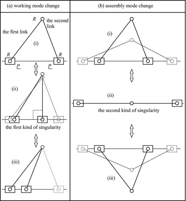
FIGURE 2.
Assembly and working mode change of 2PRR parallel robot.
KINEMATICS OF THE PARALLEL ROBOT
As mentioned before, the parallel robot can expand its workspace by the mode change. However, parallel robot encounters the singular configuration between the mode changes. In this section, kinematics and singular configuration of a 2PRR parallel robot are shown in Figure 3. Coordinate frames Σ0 and Σi (i = 1, 2) are defined for the fixed coordinate and position of each actuator, respectively. Vector bi is defined for the position of the origin Σi with respect to the coordinate Σ0. In the case of the 2PRR parallel robot in Figure 3, bi = 0 (i = 1, 2) because each coordinate Σi is coincident with Σ0. Unit direction vector and displacement of the linear actuator are defined as ui and qi, respectively. Unit direction vector and length of the rod are defined as wi and li, respectively. Position of the hand (output link) is given as
![]()
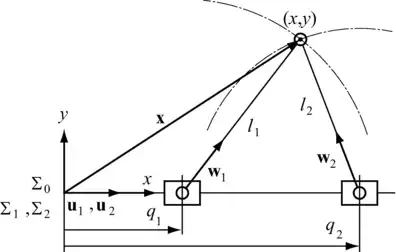
FIGURE 3.
Kinematic model of 2PRR parallel robot.
Equation (1) is the loop closure equation of the parallel robot. Next, the forward displacement analysis and inverse displacement analysis of the parallel robot are going to be derived.
Eq.
(1) is deformed as![]()
The unit
direction vector wi is eliminated by raising the both
sides of Eq. (2) to the second power as,![]()
As shown in Figure 3, ui
and bi are given as,![]()
Substituting Eq. (4) into Eq. (3), one obtains a quadratic equation about the displacement of the actuator as,
![]()
Solutions of the inverse displacement analysis are given by the solution of Eq. (5) as,
![]()
Eq. (6) represents that there are two solutions for the inverse displacement analysis. It means that the parallel robot has two working modes. Figure 2(a) (i) and (iii) represents the configurations of the parallel robot of the two working modes.
In the forward displacement analysis, positions x and y of the hand are solved by the simultaneous equations about Eq. (1) of each arm as,
![]()
Each equation of (7) represents that a circle of the central position is (qi, 0) and the radius is li. The solution of Eq. (7) is given as the crossing point of the two circles. There exist two crossing points of the circles; namely, the parallel robot has two assembly modes. Figure 2(b) (i) and (iii) represents each configuration of the assembly mode of the parallel robot.
When y = li, at that time, the value in the square root in Eq. (6) becomes zero and the inverse displacement analysis has a duplication solution. When y > li, at that time, value in the square root in Eq. (6) becomes negative and the inverse displacement analysis has no solution. When the distance between the two circles of Eq. (7) equals (li + l2), the forward displacement analysis has a duplication solution. When the distance between the two circles of Eq. (7) becomes larger than (li + l2), the forward displacement analysis has no solution.
SINGULARITY ANALYSIS OF THE PARALLEL ROBOT
Differentiating the both sides of Eq. (1) with respect to time, one obtains
![]()
In Eq. (1), bi, ui, and li are constant values and their time derivatives become zero. Because wi is unit direction vector, one obtains
![]()
Differentiating the both sides of Eq. (9) with respect to time, one obtains
![]()
Multiplying the both sides of Eq. (8) by wiT and taking into consideration about Eq. (9), one obtains
![]()
The displacements of all actuators q1 and q2 are defined by vector form as q = [q1 q2]T; then, Eq. (10)is expressed by matrix form as
![]()
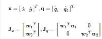
Jx and Jq are the Jacobian of the parallel robot.
When the Jacobian matrix Jx becomes singular, namely the determinant of the Jacobian becomes zero as
![]()
Then, the parallel robot is in the second kind of singularity or in direct kinematics singularity. The 2PRR parallel robot occurs in the second kind of singularity when the direction of the two rods w1and w2 becomes identical.
![]()
This case corresponds to that two rods of the parallel robot lay in one line as shown in Figure 2(b) (ii). As shown in Figure 2(b), the parallel robot encounters the second kind of singularity during the assembly mode change.
When the Jacobian matrix Jq is singular
![]()
Then, the parallel robot is in the first kind of singularity or in inverse kinematics singularity. The 2PRR parallel robot occurs in the first kind of singularity when the direction of at least one rod is perpendicular to the direction of the actuator as shown in Figure 2(a) (ii).
![]()
As shown if Figure 2(a), the parallel robot encounters the first kind of singularity during the working mode change.
The third kind of singularity occurs when both Jq and Jx are simultaneously singular. It requires certain conditions of the linkage parameter. In the case of the 2PRR parallel robot, when the lengths of the rods are identical, the third kind of singularity occurs as shown in Figure 4. The third kind of singularity is referred as the combined singularity.
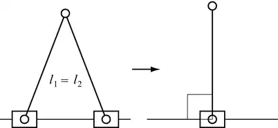
FIGURE 4.
The third kind of singularity of the 2PRR parallel robot.
PASSING THE SINGULAR CONFIGURATION DURING THE MODE CHANGES
USING THE INERTIA
As shown in Figure 5(a), if the parallel robot has some speed just before the singular configuration, the robot keeps moving according to the law of inertia; then, the parallel robot passes the second kind of singularity. Note here if the parallel robot stops at the singular configuration, it is impossible to pass the singular configuration by the inertia.
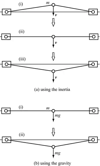
FIGURE 5.
Assembly mode change of nonredundant 2PRR parallel robot.
USING THE GRAVITY
As shown in Figure 5(b), when the gravity force acts to the lower direction, the parallel robot can pass the singular configuration even if the parallel robot stops at the singular configuration. However, the robot cannot move to the upper direction against the gravity. When the robot moves on the horizontal plane where the gravity force does not act on the robot, the parallel robot cannot pass the singular configuration.
USING THE REDUNDANCY
A robot has actuation redundancy when it is driven by number of actuators greater than the degree of freedom. The actuation redundancy may increase the cost of the robot and complexity of control. However, the actuation redundancy is one of the most effective methods for avoiding the singularity during the mode change.
Figure 6 represents 3PRR parallel robot, a planar two-dof parallel robot redundantly actuated three actuators. The Jacobian of the parallel robot is given as
![]()

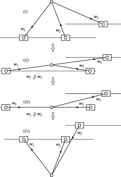
FIGURE 6.
Assembly mode change of redundant 3PRR parallel robot.
where Jx is 3×2 matrix of its full rank that equals two. For convenience, singularity analysis is applied to the 3×2 transposed Jacobian matrix of JxT. When at least one 2×2 minor of JxT is nonsingular, the rank of the Jx equals two; namely, the Jx has full rank. At this time, the robot still works as two-dof parallel robot. For example, when the first rod and the second rod are collinear as shown in Figure 6(iii), 2×2 minors of the JxT become
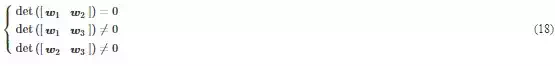
As shown in Eq. (18), one minor is singular and the other two minors are nonsingular; namely, the Jxstill has the full rank.
Now, the parallel robot loses the redundancy but keeps the nonsingularity. The parallel robot can pass the singular configuration of Figure 6 (iii). In the same way, the parallel robot can pass the singular configuration of Figure 6 (ii). Thus, the parallel robot achieves the assembly mode change from Figure 6 (i) to (iv).
The parallel robot encounters the first kind of singularity during the working mode change. In the velocity control of a robot, the velocity of the actuator is controlled to trace the desired velocity of the actuator q̇ rq̇r, which is given from the desired velocity of the end-point ẋ rẋr from Eq. (12) as
![]()
However, Jq−1 cannot be calculated when Jq is singular at the first kind of singularity. In this case, the desired velocity of the actuator is directly given instead of being indirectly given from Eq. (12).
RESEARCHES ON MODE CHANGE OF THE PARALLEL ROBOT
Researches on expanding the workspace by the mode change of the parallel robot have been reported for nonredundant two-dof planar robot, nonredundant three-dof spatial translational robot, redundantly driven three-dof translational and rotational planar robot, and redundantly driven three-dof spatial translational robot. Redundant actuation is the actuation in one of the most effective methods for avoiding the singularity. However, the redundancy is not always the answer to avoiding the singularity. Additional ingenuities, for example, path planning for mode change, or asymmetrical design for the robot, are required.