Flight Control Development and Test for an Unconventional VTOL UAV.
Ducted-fan aerial vehicles (DFAVs) have attracted much more interest of the academic and industrial communities worldwide due to their compact layout and high-security applications in several tasks such as surveillance, data acquisition, and even physical interaction within unstructured environments. Among the different possible configurations, the vertical take-off and landing (VTOL) ducted-fan aircraft is well-suited for a variety of missions in environments cluttered with obstacles or close to infrastructures and humans. This fact is motivated mainly by the ducted-fan configuration in which the propeller is protected by an annular fuselage. In addition, a prominent advantage of ducted-fan system is better overall efficiency at low speeds [1]. In this respect, also inspired by the previous works considering test-fly methods in control [2, 3], the aircraft considered here is a tandem ducted-fan vehicle configuration characterized by a very simple mechanical structure, composed only of two tandem contra-rotating propellers inside the vehicle’s fuselage, a number of control vanes which deviate the propeller’s air flow in order to obtain full controllability of the attitude dynamics (see also [1, 4]) and a set of auxiliary “direct force control” with small lateral electric ducted fans (EDFs).
Drawing inspiration from the potential of the well-designed VTOL aircraft, the focus of this chapter is on the systematic modeling, flight control development, and implementation methods of the aerial vehicle named BIT-TDF at Beijing Institute of Technology (BIT). A number of contribution focuses on the problems of feedback control design for such a class of systems. In [5], a dynamic inversion controller is proposed to govern the nonlinear dynamics of a ducted-fan aircraft. In [6], a framework of nonlinear robust control based on a path following strategy is applied to a ducted-fan miniature UAV . A structured two-loop feedback controller combined with a static anti-windup compensator is proposed in [3] for a ducted-fan aircraft. However, few research laboratories are carrying out advanced theoretical and experimental works on the system; among others, to mention a few, the European Community under the 7th Framework Programme through collaborative projects AIRobots [7], the HoverEye project of autonomous ducted-fan aircraft [8], and the Martin Jetpack [9].
To actually show the potentials in a real application scenario, the overall system design of a fully functional UAV has to be validated experimentally using a real setup, especially the proposed control techniques. The object is to consider a robust flight control design for our small-scaled ducted-fan aircraft. The proposed methods have been tested either in simulation, experimental, or both frameworks where the implementation has been carried out using the ducted-fan UAV known as BIT-TDF.
Throughout the overall development of the UAV, deriving a high-fidelity nonlinear model has been a challenging issue due to their inherent instability and large amount of high-complexity aerodynamic parameters. After the hardware construction of the ducted-fan prototype, we first obtain a comprehensive flight dynamics model based on an elaborated approach which integrates first-principle and system identification techniques. The frequency-domain identification tool CIFER [10], which was developed by army/NASA Rotorcraft Division and is one of today’s standard tools for identifying models of different aircraft configurations, has been used here to capture the key dynamics. With the identified model in hand, we then carry out to design a flight control system with two-loop architecture, in which an inner loop is for stabilization and decoupling the UAV dynamics and an outer loop is for desired velocity tracking performance. Specifically, we have combined (1) H∞ technique; (2) nonsmooth optimization algorithm; and (3) custom-defined gain-scheduling to design a nonlinear flight control law and successfully realized the automatic flight test.
Description and dynamics of the BIT-TDF system
The ducted-fan UAV of the Department of Mechanical Engineering of BIT is the BIT-TDF prototype (Figure 1a) developed by our team of researchers at Vehicle Research Centre (VRC). The front and aft propellers are enclosed within a protective carbon fiber duct to ensure safe operation of the vehicle in an indoor environment or close to building. The prototype uses a very simple, lightweight monocoque structure, producing an efficient and very durable design. The aerodynamic efficiency, in terms of additional thrust increase at the same power consumption, is improved by increasing the lip radius and decreasing the blade tip clearance. It uses eight 28-cm propellers for tandem ducted fans and standard RC motors and speed controllers. It is equipped with the COM Express Type 10 Mini Carrier Board CCG010, which is chosen as onboard flight control computer running at RT-Linux. The embedded computer system has a main processor running at 1.3 GHz, which can conveniently integrate all of necessary functions for data exchange with INS/GPS-based navigation system, servo-controller, and wireless modern, and a data acquisition board for RPM sensor. An 8-channel servo-controller (UAV100) is used to generate PWM signals necessary to drive the ducted-fan motors and the actuator servos. Custom-built real-time control software developed by the BIT VRC research group is used to real-time control the BIT-TDF.
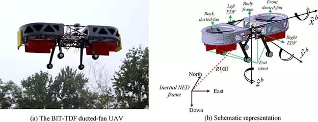
FIGURE 1.
(a) The BIT-TDF ducted -fan UAV and (b) its schematic representation.
For ease of understanding, the block diagram of the entire UAV system is illustrated in Figure 2. From left to right, it is composed of three main parts:
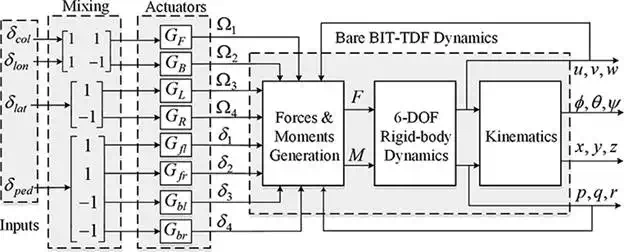
FIGURE 2.
The system block diagram.
● The first part represents the actuators along with mixing function that converts conventional pilot inceptor inputs into a combination of exit vane deflections, and motor speed. The input to this part is u = [δcol δlon δlat δped]T which are pulse-width modulation (PWM) signals. The outputs are the vector Ω = [Ω1Ω2Ω3Ω4]T representing the motor speed of front-aft ducted-fan propellers and left-right EDFs, in RPM, and the vector δ = [δ1δ2δ3δ4]T, representing the four exit vane deflections, in degrees.
● The second part is the force and moment generation mechanism block that relates the generated inputs to the applied lift, torques, and the aerodynamics acting on the system. This block corresponds to all the body components of the aircraft, that is, the tandem ducted-fan system, left-right EDFs thrust generation, vanes deflection system, and the fuselage drag part.
● The third part is the rigid-body dynamics that relates the applied force and moments to the attitude, velocity, and position of the BIT-TDF.
The subsequent sections present a comprehensive nonlinear flight model the ducted-fan aircraft.
EQUATIONS OF MOTION FOR BIT-TDF
The following flight-dynamics equations of motion describes a general physical structure based on Newton-Euler formulism, and the reader is referred to any classical flight-mechanics references for a more complete development.
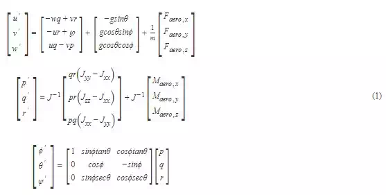
where u, v, and w are the velocities in the body frame, p, q, and r are the angular velocities in the body frame, m is the system mass, and Jxx, Jyy and Jzz are the moments of inertia along body-frame main axes. ϕ, θ, and ψ are the roll, pitch, and yaw Euler angles. Faero and Maero are the vector of external aerodynamic force and moments, respectively, which are given by
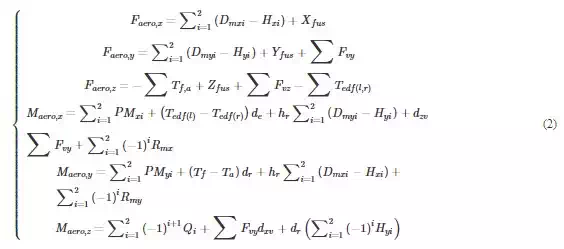
where the index i = 1 for front ducted-fan, i = 2 for aft ducted-fan, Dm for the momentum drag, H for the hub force, (□)fus for the fuselage, ∑Fv∑ for the exit vane, Tf,a for the thrust of front and aft ducted-fan, Ted(l) and Tedf(r) for the thrust of left and right EDF, PM for the duct pitching moment, Rmfor the rolling moment of a propeller, Q for the propeller anti-torque moment, and the de, hr, dzv and dxvare all the distance parameters related to torque. They are introduced in detail as follows.
The aerodynamic forces and moments are derived using a combination of ducted-fan inflow model and blade element theory. In ref. [1], one comprehensive and creative inflow model for computing ducted-fan thrust T and induced velocity vi is proposed. Such procedure is based on some modifications of classic momentum theory inflow of an open propeller. For easier reference, we list the inflow model but there involves a revised derivation of the equation of conservation of energy.
An illustration of the inflow model is shown in Figure 3. The velocity vectors upstream of the propeller, at the disk of the propeller, and far downstream of the propeller are shown below.
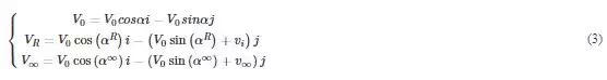
The affected angles of attack, αR and α∞, are modeled as a function of the flow turning efficiency factors kχR and kχ∞, which are given by
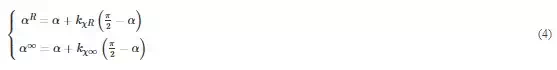
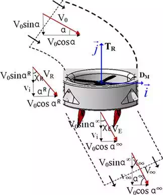
FIGURE 3.
Inflow model illustration.
The thrust of ducted-fan system is a combination of propeller thrust TR, and duct thrust TD,
![]()
where kaug is the thrust augmentation factor.
The mass flow rate of air through the duct is given by
![]()
where ρ is the local air density and AD is the duct area at the plane of the propeller.
By considering only the vertical component of conservation of momentum from free-stream flow to the far-wake flow, the expression for thrust is given by
![]()
Similarly, considering only the horizontal component, the expression for momentum drag is found to be
![]()
It is assumed that energy enters the ducted-fan system through the propeller thrust and the momentum drag. Therefore, a revised equation of increment in kinetic energy is formulated here that accounts for the contribution of the propeller thrust.
![]()
Substituting the Eq. (6) into (7), an expression is derived for the velocity ν∞. Another expression for the velocity ν∞ is found by substituting the Eqs. (5) and (7) into (9). The final result after joint solution of the velocity ν∞ is given as the newly formulated inflow equation.
![]()
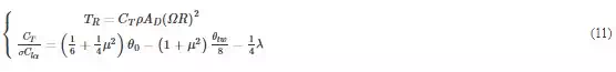
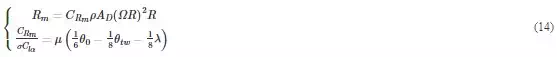
Based on the work of Gary Fay in Mesicopter project [10, 11], the aerodynamic forces and moments of rotating propeller are resolved using classic blade element theory. For convenience of the reader, we recall some symbols. σ: solidity ratio, clα: lift slope, λ: inflow ratio, μ: advance ratio, R: propeller radius, Cd¯¯¯¯: averaged drag coefficient, θ0: pitch of incidence, θtw: twist pitch. Thrust force TR is the resultant of the vertical forces acting on all the blade elements.
Hub force H is the resultant of horizontal forces acting on all the blade elements.
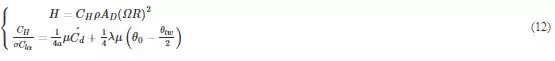
The propeller anti-torque moment Q is caused by the horizontal forces acting on the propeller that are multiplied by the moment arm and integrated over the propeller.

Rolling moment Rm of a propeller exists in forward flight when the advancing blade is producing more lift than the retreating one.
Once the thrust created by the ducted-fan system is determined from (11), the quasi-steady induced velocity is found by iterating the inflow Eq. (10), and vice versa. A simple bisection algorithm is implemented here to obtain the thrust and induced velocity. Consequently, all the forces and moments of ducted-fan system are solvable.
The exit control vanes are modeled as all-moving control surfaces that operate in the wake generated by the propellers, and provide yaw attitude control and thrust augmentation. To model those forces and moments, we refer to our mixing schematic shown in Figure 4 (also shown in the “mixing” block of Figure 2). First, we will consider all the forces generated by each vane, and then, we will consider the resultant contributions that affect the yaw dynamics. Let us denote by i = 1, …4 the each vane. There resulting force Fv and an induced moment Γv are given by
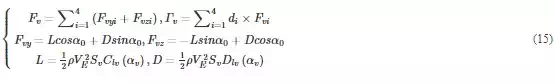
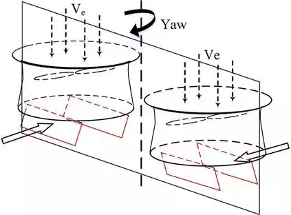
FIGURE 4.
Exit vanes used to govern yaw attitude.
where Fvy and Fvz are the aerodynamic forces projected into the body-fixed frame, α0 is the flow deflection angle and the induced moment Γv can be decomposed into the components dzv Σ Fvy and Σ Fvy dxv in (2).
There are always drag forces caused by the fuselage and have to be modeled. The fuselage drag model is a key element in the correlation with flight-test data. A function is integrated into the simulation model that calculates the fuselage drag forces along three body frame axes, which is given by
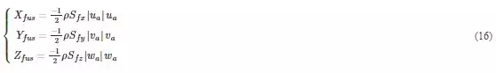
where Sfx, Sfy, and Sfz are the effective drag area in the xb, yb, and zb direction.
The two lateral small electric ducted-fans are responsible of controlling the roll attitude dynamics, regulating differential thrust on the EDFs. Specifically, a positive control input results in increased thrust on the left EDF and a decrease thrust on the right one. It should be mentioned that the previous prototype BIT-TDF in [12, 13] is a vane control mixing version, which means roll and yaw control are all achieved by deflecting the exit vanes in a mixing way. This compact VTOL vehicle was tested extensively by our research group. Although it realized basic stabilization flight, it exhibited some serious operational limitations, the most notable being its poor stability and controllability in windy conditions. Therefore, a set of auxiliary “direct force control” with small EDFs are mounted on the current prototype (see Figure 1) to optimize the system’s maneuverability. Controllability analysis and recent flight-test demonstrate that the overall performance of the newly constructed configuration has been significantly improved.
The generated thrust Tedf of the EDF is related to the PWM input upwm by a first-order linear transfer function:
![]()
where Kedf is a positive gain and τe is the time constant of EDF.
Perhaps the most challenging issue of ducted-fan system over conventional configuration is the strong nose-up pitching moment produced by the duct in edgewise flight or in presence of cross-wind. The duct pitching moment is caused by the dissymmetry lift of the duct due to the unequal flow experienced by the front and aft sections of the duct. This moment makes the vehicle so unstable that even an experienced pilot would not be able to hold it steady in flight without a stability and control augmentation system (SCAS). A meaningful observation by [1] stated that the pitching moment may be a function of airspeed, angle of attack, advance ratio, and inflow velocity. According to the experimental data in [8], the pitching moment model is implemented solely as a parabolic function of the relative airspeed for simplicity, which can be written as
![]()
where V0 is the relative airspeed, εc and εx are the constant coefficients to be determined.
Four linear servo-actuators are used to control the vane deflections, while the front and aft electronic speed controllers (ESCs) are used to control the speed of motor-propellers. The lateral EDF dynamics has been addressed in Section 2.1.4. The dynamics of all actuators can be identified in ground tests with an input of the actuator command and an output of the actuator response or the control surface deflection. However, in our case, an artificial control mixing function was used and we would like to explicitly account for this block. After examination of the respective frequency responses of the four control input channels, we see that a first-order system should adequately capture the dynamics. The corresponding differential equations are as follows:
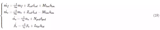
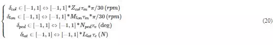
where the states mf and mr are the speed of front and aft motor-propellers, αv is the vane deflection command that is converted into a combination of four exit vane deflections, and the last state βe denotes the thrust of lateral EDF, and the corresponding time constants are τm, τv, and τe. The effective linkage gains of four input channels (Zcol, Mlon, Nped, and Llat) completely depend on the defined usable range of physical inputs that correspond to the normalized inputs in the range [−1, 1]. The equations for the effective linkage gains are as follows:
IDENTIFICATION OF MODEL PARAMETERS
From the above analysis, a full 15th-order nonlinear dynamic model can be obtained and a linear model of the BIT-TDF at the prescribed flight condition can also be extracted. We have implemented an integrated identification procedure to identify all the physical parameters. Using global optimization methods, the extracted lineal models can be utilized to tune the unknown physical parameters of the nonlinear model to match frequency responses from flight tests, which delivers a very accurate nonlinear model suitable for flight simulations, and linear models adequate for control design.
The focus of this section is on the identification results obtained by the particular CIFER tool. The frequency-domain system identification method allows for rapid updating of the vehicle response model as changes are made to the unconventional UAV designs by repeating flight tests. At first, the description of the experimental setup is given. The parameterized model with the associated stability derivatives is also provided. Then, the final results of the identification procedure follow. Finally, the accuracy of the extracted model is validated in the time domain.
The experimental platform, as depicted in Figure 5, includes an onboard flight control computer, an INS/GPS module, a sonar sensor, four high-speed brushless DC ESCs, a servo-controller, a pair of free-wave wireless data transceivers, and a ground station. The pair of transceivers establish communication between the onboard system and the ground station. The onboard system is to collect sensor data, process and fuse them, feed to the control law, send the servo-driving signals to realize desired control mode. The C code is programmed, complied, and then downloaded to the onboard system and ground system to perform specific tasks.
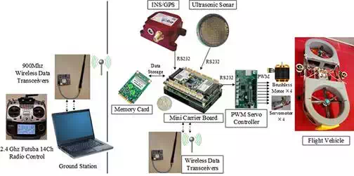
FIGURE 5.
Block diagram of the experimental platform.
The model structure of the BIT-TDF consists of 12 states. These states include eight rigid-body states and four explicit states for the actuator dynamics. The final structure is obtained first systematically eliminating the derivatives that have high insensitivity and/or high Cramer-Rao bound and then refining the model in a similar process in [14]. Figure 6 shows the system matrix A and the input matrix B of the minimum parameterized model structure.
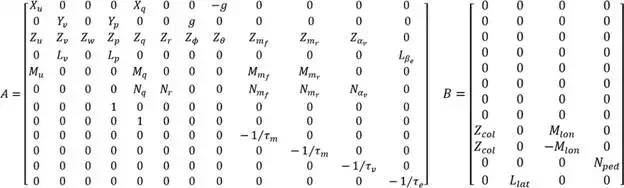
FIGURE 6.
System and input matrix for the state-space model.
The above-parameterized model provides a physically meaningful description of the system dynamics. All stability derivatives included in this model are related to kinematic and aerodynamic effects of the ducted fans, exit vanes and the fuselage. The challenge is the determination of their arithmetic values.
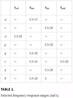
As shown in Figure 7, the data-collection experiment is performed in closed-loop with an external SCAS engaged. The reason for the closed-loop experiment arises from that the BIT-TDF is lightly damped and inherently unstable. When the ducted-fan vehicle is set to hover, we inject a set of computerized frequency sweep excitation signal to one of the four control inputs. The resulting control signals along with their corresponding output responses are inserted into the CIFER software which processes the time domain experimental data to produce a high quality multi-input multi-output (MIMO) frequency response pairs. For our BIT-TDF vehicle, the selected frequency responses and their frequency ranges are depicted in Table 1.
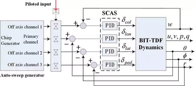
FIGURE 7.
Schematic diagram of data collection in the closed-loop setting.
The extraction of the parametric model is an iterative procedure, which continues until difference between the actual and simulation frequency responses is minimized as shown in Figure 8. The identification results illustrate the system can be well characterized as a linear process in the interested frequency range. Note that the parameters in the model structure have been designated as the following four categories:
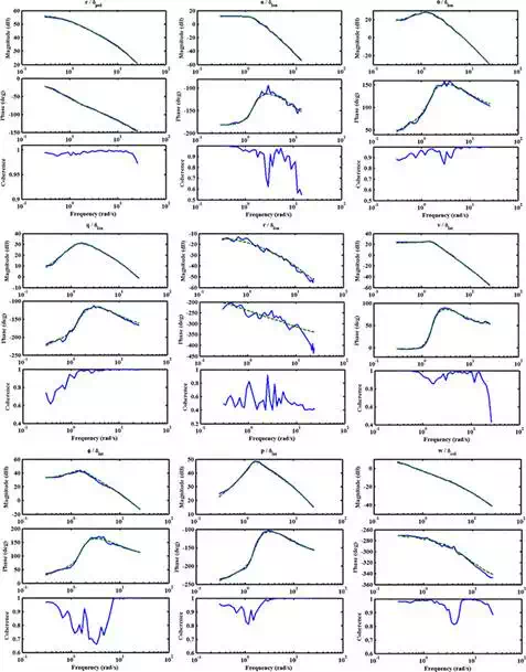
FIGURE 8.
Frequency responses for the flight data (solid line) and frequency responses predicted by the state-space model (dashed line).
● Fixed parameters known as a priori;
● Constrained parameters with constraint equations to enforce commonality and kinematic interrelationship;
● Isolated parameters that is difficult to achieve a satisfactory identification;
● Free parameters to be determined in the course of the identification.
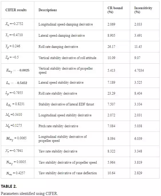
Some physical parameters, such as gravity and actuators-related parameters (determined from input-output ground tests), are known as a priori and should be fixed. Some stability derivatives in system matrix exist constrained relationships due to the symmetrical configuration, such as Zmf=Zmr,Mmf=−MmrM. There are also some parameters difficult to identify due to poor low-frequency excitation and they can be obtained based on the static trim estimation. The remaining free parameters for our vehicle are listed in Table 2, from which it is clear that all the parameters identified using CIFER are highly accurate.
Time-domain is more straightforward for evaluating the predictive capability of the identified model for test inputs, such as steps or doublets that are dissimilar with the ones used in the identification process. Four individual flight records are collected, each corresponding to one of the test inputs. The recorded inputs are used as inputs to the identified model, and the ducted-fan vehicle’s responses predicted by the model are compared to the responses recorded during the flight tests. The comparison results are depicted in Figure 9, which indicates an excellent fit between the predicted values from the identified model and the flight data.
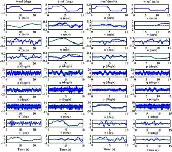
FIGURE 9.
Time-domain validation.
Robust flight control system design
During the BIT-TDF project, we explored several control approaches from theoretical development to final experiments. After the evaluation of all the control approaches tested in this project, it becomes clear that the way to follow is the systematic application of the structured robust control based on nonsmooth optimization algorithm. In fact, the newly developed nonsmooth optimization algorithm in [15] is well suited for robust control synthesis of the cascaded structure of the ducted-fan dynamics. Moreover, the fixed-structure controller is easy to implement and fine-tune within a standard flight control infrastructure based on PID feedback terms or low-order terms. In addition, the robust framework is able to elegantly reject strong disturbances and easily extended to robust gain scheduling control. After a phase of extensive simulation and experimentation, the structured robust control was proposed as a single approach for flight control system design.
FEEDBACK CONTROL CONFIGURATION
The key task of the control system is to regulate the flight velocity of the vehicle to a desired value and keep it irrespectively of the exogenous wind disturbances. However, as a matter of fact, there is a potentially countless kinds of control structure to achieve the control task. From the perspective of engineering implementation, decentralized collections of simple control elements such as PIDs, static gains, structured, or limited-complexity controllers are preferred. Moreover, it is known that most practical problems can be controlled by low-order controllers with good performance. In this context, we chose the very simple control architecture, shown in Figure 10, which consists of two feedback loops. The inner loop (static output feedback), being fully actuated, provides stability augmentation and channel decoupling. The outer loop (four PI controllers), cascaded with inner loop, is in charge of regulating the inner loop in such a way that provides proper attitude variables as virtual inputs to velocity outer loop to asymptotically approach the desired velocity references.
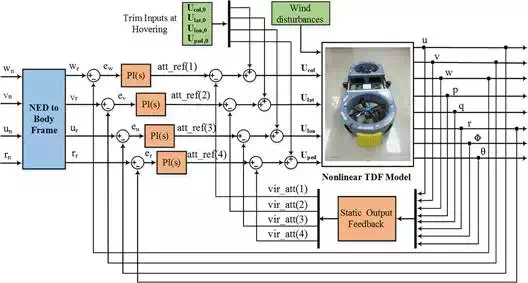
FIGURE 10.
Feedback control configuration.
GAIN SCHEDULING COMPENSATION
The control task is complicated by the fact that the plant dynamics are nonlinear throughout the flight envelope, so the flight controllers must be adjusted as a function of flight speed, which is also called the scheduling variable. As for TDF, we have selected the equilibrium conditions for five flight conditions which are corresponding to the forward flight speed u = 0, 2.5, 5, 7.5, and 10 m/s, respectively, and linearized the flight dynamics around each equilibrium. Motivated by [16], we combine the linear controllers design and the scheduled process by parameterizing the controller gains as low-order polynomials in forward flight speed and directly tuning the polynomial coefficients for the desired envelope. This approach results in a compact scheduling formula and guarantees smooth gain variations. More specifically, we use a quadratic polynomials for the four PI gains
![]()
where the three coefficients Kj0, Kj1 and Kj2 are tunable parameters, and V is the forward flight speed. We use a simple first-order polynomials for the static output feedback matrix
![]()
DESIGN OF THE STRUCTURED CONTROLLER
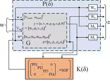
FIGURE 11.
LFT of an augmented system and a structured controller.
Using simple block diagram manipulations, we can transfer the initial control architecture of Figure 10into a design-oriented form as illustrated by Figure 11, which is known as the standard lower linear fractional transformation (LFT). Two exogenous inputs, wind disturbances and reference signals, are gathered in W, and exogenous performance-related outputs, the weighted error signals and actuator effort signals, are gathered in Z. δ denotes the gain scheduling variable, which is the forward flight speed in our design case. P is the augmented linear parameter-varying plant composed of the original plant dynamics and the weight filters used to express the control objectives. K is the controller to be designed and scheduled as a function of δ. The structured controller K is just a reformulation of the architecture described in Figure 10. That is, the outer-loop PIs and inner-loop static output feedback form the components 4-by-4 diagonal PI block and the negative constant matrix-SOF, respectively, of the compound controller K.
The H∞ control problem is formulated as the following program
![]()
It should be emphasized that when smaller and more practical controller space K are chosen as in the compound controller K, the problem (23) is much harder to solve and this is exactly the reason for adoption of nonsmooth optimization techniques.
For good tracking accuracy, the weights associated with each outputs should include integral action at low-frequency range and a finite gain at high frequencies is useful in reducing overshoot. Therefore, the following high-gain low-pass filters are selected
![]()
For attenuating noise, increasing robustness to unmodeled dynamics, and preventing high-frequency control activity that would saturate the actuator physical limits, the following high-pass filters Wu are selected
![]()
We also consider the multivariable stability margins also called disk margins discussed in [17], which can be viewed as robustness against simultaneous gain and phase variations at both the plant inputs and outputs. The target gain and phase margin values are converted into a normalized scalar function to be minimized
![]()
where x(s) = (1 + L)(1 − L)−1, D is a diagonal scaling matrix to be computed during the iteration process, L is the corresponding open-loop response to be shaped, and the parameter α is the minimum distance between the open-loop response and the critical point. Here, we impose a minimum distance of 0.6, which guarantees margins of nearly 5dB and 40°. Note that the weighted function blocks Mu and My (see Figure 11) are exactly used to express the stability margins requirement.
The resulting control problem of (23) is concretely rewritten as the following nonsmooth program
![]()
where x is the decision variable in the space formed by collecting all tunable entries in the structured controller, m denotes a given operating point of the objective flight envelope, the function fm (x) and gm(x) are of the following form
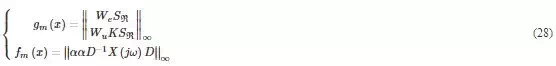
where SRSR is the closed-loop sensitivity function from setpoints to tracking errors.
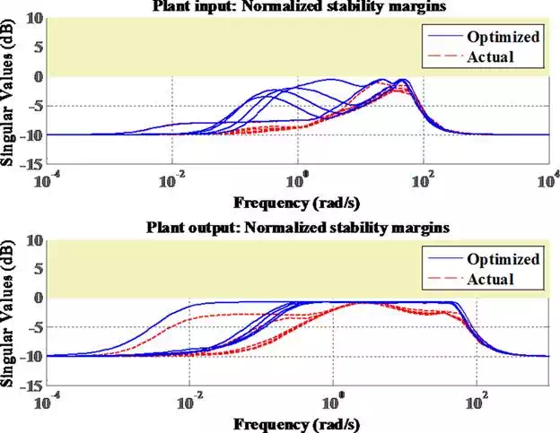
FIGURE 12.
Multivariable stability margins.
The structured robust controller synthesis is carried out in the framework of the nonsmooth H∞optimization algorithm using the MATLAB Hinfstruct solvers. After some trail-and-error iterations and design repetitions, the smallest values of L2 gain of hard constraint gm(x) and soft constraint fm(x) are found to be 0.9994 and 0.935, which indicates the resulting design satisfy all the design requirements. A visual inspection of the multivariable stability margins can be seen in Figure 12. The yellow region denotes margins that violate the requirements. The blue plot represents the margin objectives to be optimized in the calculation process, which is an upper bound on the actual margin. Note that the five different curves represent the five discrete operating points. The actual stability we obtained in the red dotted lines indicate that the stability margin requirements are satisfied at all frequencies in the designed fight envelope. The frequency responses related to the hard constraints are shown in Figure 13, which indicates the disturbance rejection and tracking errors at low frequencies are expected to perform well and fast actuator movement can be effectively suppressed inside the closed-loop bandwidth.
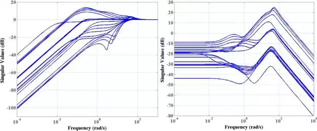
FIGURE 13.
Singular value plots for the closed-loop transfer functions (left for S and right for KS).
Simulation and flight test results
The simulation and experimental tests have been carried out in the ARC flight arena at Beijing Institute of Technology. The employed hardware architecture for the experimental validation is briefly introduced in Section 2.1.1. A variety of simulation tests have been conducted before actual flight experimentation. As a representative example show in Figure 14, we present the gust alleviation effects of the closed-loop system for hovering flight. The strong wind gust has been intentionally injected into the x-, z-, and y-axis of the body frame, with the peaking amplitude of 9, 3, and 7 m/s, respectively. The system response clearly demonstrates that the wind gust effect has been effectively attenuated.
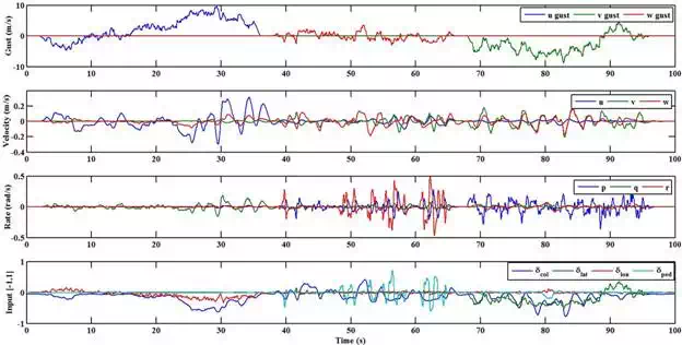
FIGURE 14.
Simulation results of wind gust alleviation effect at hovering.
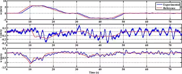
FIGURE 15.
Flight test-velocities.
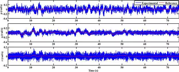
FIGURE 16.
Flight test-angular rates.
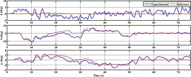
FIGURE 17.
Flight test-Euler angles.
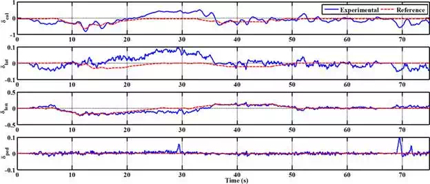
FIGURE 18.
Flight test-control inputs.
The experiment proposed in this part consists of an accelerated flight maneuver after a short-time hovering flight. The desired maneuver is a horizontal forward and inverted flight with a trapezoidal velocity in the longitudinal direction of the inertial frame. Throughout the maneuver the desired heading rate remains constant with the value rd = 0. The resulting responses versus the reference signals are illustrated in Figures 15–18. The test results show that the predefined flight maneuver can be well achieved with small fluctuation of the actual responses from the reference signals. Such fluctuations are within an acceptable range, which is mainly caused by the limited accuracy of the output feedback measurement signals. A certain degree of deviations between the control input signals are due to both the model uncertainties and the gust disturbances during the flight test.
Conclusion
Summarizing, it can be stated that, following systematic design and implementation of BIT-TDF, including unconventional configuration design, hardware and software development, frequency-domain identification as well as navigation and control algorithms, it is expected that flight control development described in this chapter would have successful application in support of Unmanned Aerial Vehicle UAV development. The main concern is to propose approaches that can be effective, easy to implement and to run onboard the UAVs. The proposed flight control law has been implemented and tested with the BIT-TDF ducted-fan vehicle and current work aims to propose and implement more advanced and practical techniques. Considering the requirements on various practical implementations, extensive contributions could be achieved by extending the BIT-TDF research in physical interactions with the environment in terms of desired or even unpredictable contacts.