The LM393 Voltage Comparator Chip
When building a light sensing robot, it is necessary to include a comparator chip that compares the pair of sensors located on the breadboard. An LED is lit up depending on the difference in voltage between the sensors.
Introduction
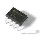
In a general sense, an analog voltage comparator chip is like a small voltmeter with integrated switches. It measures voltages at two different points and compares the difference in quantity of voltage. If the first point has a higher voltage than the second point, the switch is turned on. However, if the first point has a lower voltage than the second point, the switch is turned off. Although there are different models of voltage comparator chips, I will discuss a very common comparator, the LM393.
What does LM393 stand for?
LM393 stands for “Low Power, Low Offset Voltage, Single Supply, Dual, Differential Comparators." I will define each part:
○ “Low Power" is an indication that the chip uses little electricity. This can be very useful for a robot that runs on low voltage batteries.
○ “Low Offset Voltage" is an indication that the chip can compare voltages of points that are very close together.
○ “Single Supply" is an indication that the chip uses the same power supply as the points being compared.
○ “Dual" is an indication that there are two comparators in the chip.
○ “Differential" is an indication that the chip is comparing the amount of voltage of each point to each other and not comparing the voltage to a set value, such as below 4.0 V.
Examining the Datasheet
Each voltage comparator chip has a datasheet that includes important information about features of the part and how it is an improvement over previous models of that part. Engineers find the datasheet very useful, as it indicates specific aspects of the comparator that were not present before. Furthermore, the datasheet states average and maximum values for certain aspects, including the amount of current the comparator uses, the comparator’s optimal voltage range, and the comparator’s optimal temperature range. The datasheet provided for the LM393 states that it has an optimal voltage range of 2 V to 36 V. This makes the LM393 suitable with a 9 V battery, since this battery has a voltage range of approximately 5 V to 10 V.
Datasheets for the LM393 can be downloaded here: http://www.datasheetcatalog.com/datasheets_pdf/L/M/3/9/LM393.shtml
Analyzing the Pinouts
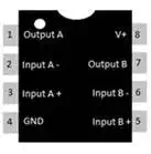
If you inspect the LM393 comparator, you will notice metal wires that stick out. These are called pins. Undoubtedly, the most significant information about a comparator chip is how to connect the pins to the rest of the components in a circuit. Since the LM393 comparator chip is too small for an indication of the pins to be printed, the datasheet has an illustrated figure, a pinout, which shows the location and function of each pin. The figure to the right shows the pinout for the LM393 comparator.
Conclusion
When building your own robot on a solderless breadboard, one of the components of the robot will be its brains. Part of this component can be a comparator chip, depending on the type of robot you’re building. The discussion on the LM393 comparator chip, which is frequently used by robot builders, is directed to those who are interested in building a light sensing robot, but is still useful for all who wish to incorporate a voltage comparator chip in their robot.