Measuring Resistance of Resistors
For any beginners in robotics, or even experienced individuals, being able to determine the resistance value of a resistor is important in building a robot, or more specifically an electronic device.
Converting Colors to Numbers
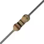
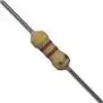
Before we begin measuring the resistance of resistors, it would be very helpful if we know how to distinguish between the different resistors. Resistors have an assortment of colored bands that indicate their value. The chart below shows all the possibilities. Click it to enlarge it.
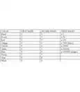
Using this chart, a resistor with the colors yellow, violet, and brown, would be 47 x 10 = 470
Moreover, if the resistor has four colored bands, the last color will indicate the tolerance. The chart below shows the tolerance for different colors. Click it to enlarge it.
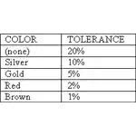
The tolerance of a resistor will tell you the range of value expected from it. For instance, a 5% tolerance on a value of 100 indicates that it could actually be anywhere between 95 and 105.
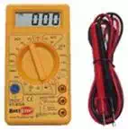
To measure the resistance of a resistor, one must have a multimeter handy. The following steps should be followed in order to correctly measure the resistance:
1. Switch the dial to the 200 Ω range, if it is not already there.
2. The black lead must be connected to the COM terminal.
3. The red lead is connected the terminal labeled Ω. This may vary for different models, so consult your specific instructions.
4. Turn the meter on.
5. Obtain a 100 Ω resistor. The color bands will be brown, black, brown, and gold which is the proper order.
6. Connect the tip of the black probe to one end of the wire of the resistor. The end you choose is arbitrary.
7. Connect the tip of the red probe to the other end of the resistor wire.
If you happen to have them, alligator-clips or hook adapters would be very useful for meter test probe tips. Otherwise, it is difficult to touch each wire end of a resistor with both probe tips simultaneously.
Interpreting the Resistance Displayed on the Meter
Ideally, the meter should be displaying 100 Ω. It is likely that the meter will read a value slightly lower or higher than 100. However, if the meter displays 0L or an unusually large number, then you should ensure the setting for the dial is at ohm, if that is the setting for your particular multimeter. Jiggle the test probe connections so that the connection is properly established. Or, you may have the color bands in the wrong order. The correct order is specified in step 5. But if the multimeter is in working order, then the resistor may be the cause for the unusual readings. Resistors are not resistible to ageing, temperature extremes, shock, and other such mistreatment. Still, it is unlikely that a new, 5% tolerance, 100 Ω resistor would give readings outside the 95-105 Ω range. To be certain, test several more resistors.
Experiencing Resistance Ranges
8. Obtain a 470 Ω resistor, of which the color bands are yellow, purple, brown, and gold.
9. With a manual ranging multimeter, choose an ohm range less than 470 on the meter.
10. Connect the 470 Ω resistor the same way you did the 100 Ω resistor.
Choosing a low maximum range with the dial is not harmful to the multimeter as is choosing an inappropriate voltage range. Nonetheless, a manual-ranging meter will not be able to display the measurement of the resistance. Typically, 0L will be displayed instead. Due to the need of frequently testing different ranges on the manual-ranging meter, it will be tedious to determine the resistance of a box of resistors. This job is made much easier with an auto ranging meter.