Essential Features Of A Water-Power Plant
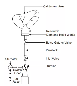
A simplified flow sheet of a water power plant is shown in Fig: The essential features of a water power plant are as below:
1. Catchment area.
2. Reservoir.
3. Dam and intake house.
4. Inlet water way.
5. Power house.
6. Tail race or outlet water way.
1. Catchment Area. The catchment area of a hydro plant is the whole area behind the dam, draining into a stream or river across which the dam has been built at a suitable place.
2. Reservoir. Whole of the water available from the catchment area is collected in a reservoir behind the dam. The purpose of the storing of water in the reservoir is to get a uniform power output throughout the year. A reservoir can be either natural or artificial. A natural reservoir is a lake in high mountains and an artificial reservoir is made by constructing a dam across the river.
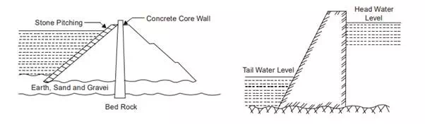
3. Dam and Intake House. A dam is built across a river for two functions: to impound the river water for storage and to create the head of water. Dams may be classified according to their structural materials such as: Timber, steel, earth, rock filled and masonary. Timber and steel are used for dams of height 6 m to 12 m only. Earth dams are built for larger heights, upto about 100 m. To protect the dam from the wave erosion, a protecting coat of rock, concrete or planking must be laid at the water line. The other exposed surfaces should be covered with grass or vegetation to protect the dam from rainfall erosion. Beas dam at Pong is a 126.5 m high earth core-gravel shell dam in earth dams, the base is quite large as compared to the height. Such dams are quite suitable for a pervious foundation because the wide base makes a long seepage path. The earth dams have got the following advantages.
(a) Suitable for relatively pervious foundation.
(b) Usually less costlier than a masonary dam.
(c) If protected from erosion, this type of dam is the most permanent type of construction.
(d) It fits best in natural surroundings.
The following are the disadvantages of earth dams :
(a) Greater seepage loss than other dams.
(b) The earth dam is not suitable for a spillway; therefore, a supplementary spillway is required.
(c) Danger of possible destruction or serious damage from erosion by water either seeping through it or overflowing the dam.
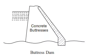
The masonary dams are of three major classes: solid gravity dam, buttress dam and the arched dam.
The buttress or deck dam has an inclined upstream face, so that water pressure creates a large downward force which provides stability against overturning or sliding. An arch dam is preferable where a narrow canyon width is available. It can be anchored well and the water pressure against the arch will be carried by less concrete than with a straight gravity type. This dam has the inherent stability against sliding. The most commonly used dams are shown in Fig.
Dams must be able to pass the flood water to avoid damage to them. This may be achieved by : spillways, conduits piercing the dam and the tunnels by passing the dam.
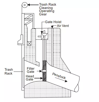
The intake includes the head works which are the structures at the intake of conduits, tunnels or flumes. These structures include booms, screens or trash racks, sluices for bypassing debris, and gates or valves for controlling the water flow. Booms prevent the ice and floating logs from going into the intake by diverting them to a bypass chute. Booms consist of logs tied end to end and form a floating chain. Screens or trash racks are fitted directly at the intake to prevent the debris from going into the intake. Debris cleaning devices should also be fitted on the trash racks. Gates and valves control the rate of water flow entering the intake.
The different types of gates are radial gates, sluice gates, wheeled gates, plain sliding gates, crest gates, rolling or drum gates etc. The various types of valves are rotary, spherical, butterfly or needle valves. A typical intake house is shown in Fig. 11.5. An air vent should be placed immediately below the gate and connected to the top of the penstock and taken to a level above the head water. When the head gates are closed and the water is drawn off through the turbines, air will enter into the penstock through the air vent and prevent the penstock vaccum which otherwise may cause collapsing of the pipe. A filler gate is also provided to balance the water pressure for opening the gate.
4. Inlet Water Ways. Inlet water ways are the passages, through which the water is conveyed to the turbines from the dam. These may include tunnels, canals, flumes, forebays and penstocks and also surge tanks. A forebay is an enlarged passage for drawing the water from the reservoir or the river and giving it to the pipe lines or canals. Tunnels are of two types: pressure type and non-pressure type. The pressure type enables the fall to be utilized for power production and these are usually lined with steel or concrete to prevent leakages and friction losses. The non-pressure type tunnel acts as a channel. The use of the surge tank is to avoid water hammer in the penstock. Water hammer is the sudden rise in pressure in the penstock due to the shutting off the water to the turbine. This sudden rise in pressure is rapidly destroyed by the rise of the water in the surge tank otherwise it may damage or burst the penstock.
5. Power House. The power house is a building in which the turbines, alternators and the auxiliary plant are housed.
6. Tail Race or Outlet Water Way. Tail race is a passage for discharging the water leaving the turbines, into the river and in certain cases, the water from the tail race can be pumped back into the original reservoir.