Undercuts In Plastic Injection Molding
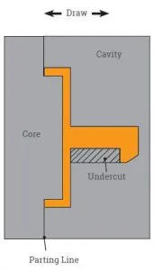
When designing for plastic injection molding, undercuts can be used to carry out complex forms of molding such as the overmolding process and insert molding process. An undercut is any indentation or protrusion that prohibits part ejection from a mold. It is a feature that cannot be captured with the cavity and core alone. It is die-locked which prevents the part from being ejected from the cavity.
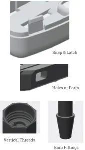
Some of the more common ways to use undercuts are to create interlocking or snap and latch features. This allows for clamshell or housing designs to come together for quick and easy assembly. Another way to use undercuts are to capture side holes or ports for wiring, button features or assembly. More common ways to use undercuts are to capture vertical threads and barb fittings typically used in medical device products.
Undercuts can also be used to core out thick sections that cannot be captured by the core and cavity alone. This prevents the possibility for sink and warp. Finally, undercuts can be used to provide threaded and custom inserts that are not in the line of draw. The insert itself can sometimes create undercuts.
A thorough DFM can be provided by your manufacturer to identify problematic areas within the undercut features. Therefore, it’s best to design it as you intend it and to keep the functionality of your design.
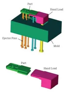
Undercuts are commonly used in medical parts. At left, is a medical part with some key features. The internal threads on this part uses a side action to unscrew from the part after the injection process to create these threads. Be sure to continue threads throughout the entire interior of the part so the interior hand load will not be die-locked and can be easily removed. Internal threads must be captured by a hand load that is removed manually from the part after molding.
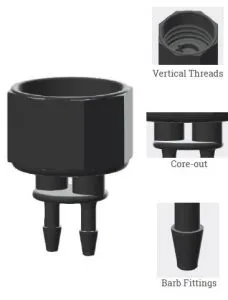
Keep in mind, the space between the inlet ports also require a special undercut called a core-out. Core-outs are used to keep wall thickness even and are a planned aspect of the design. The barb features are another classic yet complex undercut feature for medical parts because they are necessary for tubing. Most manufacturers will mold this so that the barb is parallel to the parting line. At Xcentric, we use a rather complex undercut that includes a pin assembly to allow for venting and capture the barbs perpendicular to the parting line. The venting will prevent gas trapping and air burning which creates short shots at the tip of the barb feature.
Below is a cell phone housing that contains many undercuts. All the holes located on the side of the housing are considered to be undercuts. These functional features include buttons, port holes and hinges. However, each undercut adds to the complexity of the mold.
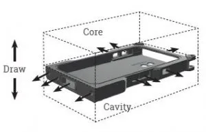
There are also some recessed areas that we call internal undercuts which are areas inside the part that cannot be captured from outside the part. Internal undercuts can be the most difficult type of undercut for a manufacturer to capture. Special considerations must be made for allowing enough space for their removal.
If you are including undercuts when designign for plastic injection molding, consider the following requrements to help ensure success.
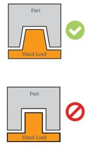
Part features that can only be captured by hand loads or side actions have design requirements. The first requirement is space. Design your undercut feature (button, port hole, etc.) with enough space so that the hand load can be removed without obstruction. If there is not enough space, the hand load will be die locked and will not be able to be removed.
Secondly, design your part so that the molder is able to effectively pinch the hand load or side action with the cavity and core. This will result in a tight shut-off which is imperative to reducing parting line flash. A final requirement is to add enough draft to your undercut feature so that it can be removed from the mold easily.
Some of the challenges involved with molding parts with undercuts are that non-drafted areas can be difficult to remove. Demolding parts with insufficient draft will make it difficult to remove the side action manually. However, if the draft cannot be increased, the hand load can be coated with nickel-plating which allows for a more non-abrasive connection between the part and the hand load making removal easier.
Certain materials can also be challenging when incorporating undercut features. Some materials, like glass filled plastics, are more difficult to pull from the mold. In general, the harder the material, the harder the pull. So, it is essential to put as much draft as possible when using these harder materials.
Finally, cosmetic surfaces with undercuts will be hard to maintain due to increase parting line exposure from the hand load. When designing undercut features that lie on the cosmetic side, it’s recommended to reduce the amount of parting lines on the outside by utilizing an internal undercut.
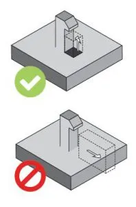
As undercuts add complexity to the mold, it also adds cost. It’s recommended to try and eliminate unnecessary undercuts when possible by designing part features that are perpendicular to the draw line. Below are some drawings to help you visualize ways to avoid an unnecessary undercut.
We use hand loads for speed and time to market. This also depends on the part geometry or whether or not it is an external or internal undercut. The auto-slide is implemented based on a longer cycle production to reduce overall per part cost. If speed is essential, we use manual hand loads.
Always model your part the way you need and intend for it to be. Keep in mind the tips outlined in this book, but build your model with good molding intent. From there, a good manufacturer can help tweak the design to function well in the tool building and molding process including those undercuts.