Fractionation of Polymers
Introduction
In the working group of Professor Wolf two different kinds of polymer fractionation techniques were developed. They allow the production of large amounts of material with narrow molecular weight distribution (MWD) starting from material with a much broader MWD. The fractionation principle is for both methods the same. It will be explained for the special case of a single solvent and for the (in real life) easier to deal with mixed solvent systems. Basing on the earlier invented Continuous Polymer Fractionation (CPF), the so called Continuous Spin Fractionation (CSF) was developed in 2002. For the CPF a filled column is used to carry out a counter-current extraction. The main feature of the CSF is the use of spinning nozzles. For both methods we will show a schematically apparatus. Some practical examples of different polymers will be listed below.
Binary system: polymer and a single solvent
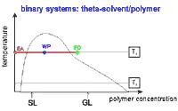
A homogeneous solution of the polymer is used as feed (FD) and the pure theta solvent as extracting agent (EA). The flow rates of these two liquids are chosen in such a manner that the total composition of the mixture within the apparatus corresponds to a point inside the miscibility gap (WP: working point of the fractionation). Then, the two phases formed in the column coexist throughout the process, and the polymer originally contained in the feed spreads into the phase originating from the extracting agent. During this process the polymer species of lower molecular weight are preferentially removed from the feed. Because of the counter-current nature of the process, the partition of the polymeric species takes place repeatedly, until the feed essentially contains only components of higher molecular weight. This phase, a concentrated solution, denoted as gel (GL) leaves the apparatus at its lower end. The phase mainly formed from the extracting agent (dilute solution, denoted as sol (SL)) has taken up the corresponding material of lower molecular weight and leaves the apparatus at its upper end.
click to enlarge picture
|
Fig. 1. Schematic phase diagram to explain the operation of polymer fractionation with a single solvent. At a fixed temperature T1, a highly concentrated polymer solution (FD) is extracted continuously with pure solvent (EA); the flow rates are so chosen as to give an overall concentration (working point) within the (shaded) two-phase region. |
If the desired narrow MWD of the fractions cannot be obtained in a single run, it is possible to use the gel directly as feed for the next fractionation step.
Ternary system: polymer and a mixed solvent
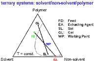
Figure 2 shows the situation of the polymer fractionation for the normally used mixed solvent. Here the polymer is dissolved in a solvent / non-solvent mixture and this solution (FD) is extracted by a liquid (EA) which contains the same mixed solvent as the feed.
click to enlarge picture
|
Fig. 2. Schematic phase diagram to explain the polymer fractionation in the case a mixed solvent is used; the Gibbs phase triangle shows the typical compositions of the phases entering (FD, EA) and leaving (GL, SL) the fractionation apparatus. |
With this method, as compared with conventional counter-current extraction, the alternative for the polymer molecules of different molecular weight is not to be dissolved in either of two solvents, but to be enriched in the more dilute or the more concentrated phase, both of which contain the same solvent.
Continuous Spin Fractionation (CSF)
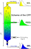
In the case of the CSF the feed is pressed through a spinning nozzle into a properly chosen extracting agent. The threads of the viscous polymer solution disintegrate shortly after their exit into tiny droplets from which the better soluble macromolecules can be easily extracted because of the short distances of transport and successful fractionation becomes possible even with rather concentrated polymer solutions. The droplets, freed from the low molecular weight material, contain the gel fraction whereas the saturated continuous phase comprises the sol fraction.
click to enlarge picture
|
Fig. 3. Scheme of the apparatus used for CSF. Feed and extracting agent are transported by means of two precision pumps at the rate required to realize the desired working point and the feed is spun through a spinning nozzle into a heavily stirred vessel. The two phase mixture produced in this manner flows freely into a column where the polymer rich gel phase (GEL) sediments and leaves at the lower end, whereas the polymer lean sol phase (SOL) exits at the upper end. The differential molecular weight distributions are shown color-coded in the inserts. |
Continuous Polymer Fractionation (CPF)
CPF can, in principle, be performed with any apparatus for counter-current extraction. So far, the experiments have been mainly carried out with a modified commercially available sieve bottom column with pulsator, a packed column, a mixer-settler system, or a centrifugal separator.
click to enlarge picture
|
Fig. 3. Schematic representation of a CPF-column for a column packed with glass beads: Upon pumping FD and EA in a proper ratio into such a device at the indicated positions, two phases are formed and - if their densities differ sufficiently - transported through the column by gravity so that they can be collected as gel (GL) and as sol (SL) at the opposite ends of the apparatus. For Systems which phase separate on cooling, T2<T1 ; in the case of phase separation on heating, T2>T1. |


