10 Common Plastic Processing Techniques
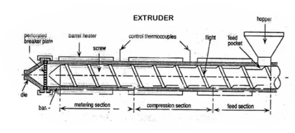
01.Extrusion
Extrusion is most commonly used in the plastics processing industry. But, metals such as steel, aluminum, brass copper, lead, magnesium can be extruded. Extrusion gives fixed cross-sectional profiles. The shape of the cross-section is determined by the shape of the die. Die can be changed according to the condition. These dies are connected to the end of the extruder. Generally, uses for wire coating.
The extruder is the main part of several processing techniques.
02.Compression molding

Mold has two plates. The bottom part of the mold has a cavity. The shape of this cavity is similar to the product which is going to be molded. Heat is supplied to the mold electrically or using steam depending on the heat requirement. Before applying the material into the mold, both plates of the mold are heated. The next step is opening the mold and filling the material into the cavity. Before filling the cavity, the required volume of the material should be calculated according to its density. In order to fill the cavity properly, an excess of 5% of the material will fill into the cavity.
Then the mold is closed and pressure is applied. But all the pressure is not applied initially. Pressure is increased step by step. After all the pressure is applied, mold is let for 2-8 minutes for proper molding. Then, excess material will flush outside. If the material is thermoplastic, it can be reused. If the material is curable cannot reuse, but it can be used to calculate the vulcanizing percentage. This value is not an exact value, but we can get a rough idea about the vulcanizing percentage.
The next step is cooling. Some machines have a cooling system. Mold can be cooled electrically for curable materials. Then the mold will open and eject the material.
03.Injection molding
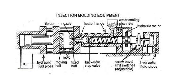
Injection molding equipment has both moving and stationary parts. Injection molding equipment is almost similar to the extruder. Parts of the injection molding machine are clamp, mold, barrel, Injector, and hopper.
The screw of the mixing chamber has a special character. So, it can move both forward and backward. The screw moves backward while rotating and it comes forward without rotating. The injection of the material will take place due to the movement of the screw.
Mold has two halves of plates. One plate is stationary and the other one can move backward and forward. When injecting the material into the mold, two plates of the mold come together. After filling the cavity of the mold, cooling of the product occurs. Then the mold is opened by moving the movable part of the mold. So, the product will remove from the mold.
Moving plate moves on the tie bar due to hydraulic pressure coming from hydraulic fluid pipes.
The mold is replaceable. Mold can be changed according to the product. To increase the efficiency of the machine multi-impression injection molding process is used. in such a process, more than one mold is connected to the machine. This method is more efficient, but the wastage is high. Because there are remaining materials in runners. This material is also cooled when cooling the product and will be discarded. But if it is thermoplastic, it can be recycled.

Reaction injection molding
Reaction injection molding is a special type of injection molding. The difference of the machine is the mold is injected with monomers. The polymerization process occurs in the mold cavity.
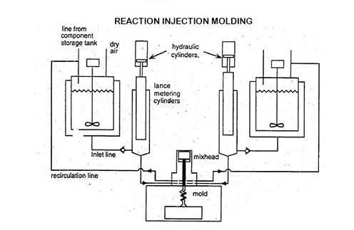
When polymerizing polyurethane “Diisocyanate” is used as a monomer. It is very toxic and can be easily transferred into the human body. So, reaction injection molding is a safe processing technique to process such polymers.
04.Thermoforming

Thermoforming is a process in which the material is processed at a rubbery state. This is a very simple process. Mold can be wooden because low heat is applied. Simple profiles such as Yogurt cups, toy cars, lunch packs can be manufactured by thermoforming.
Mold has the shape of the product. A plastic sheet is placed above the mold and heat is applied until the material became a rubbery state. At the base of the mold, there are vents (one or two) and those vents are connected to a vacuum. Due to the vacuum. The plastic sheet moves towards the mold and takes the shape of the mold.
To increase the efficiency of the machine, several molds can be used in a single processing cycle.
05.Blow molding
There are two types of blow molding. Those are
· Extrusion blow molding
· Injection blow molding
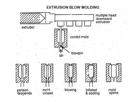
Extrusion blow molding
Molds are connected at the end of an extruder. Several molds can connect at a single processing cycle. The mold has two parts that can move towards and away from each other. Tube shape molten material insert into the mold. To get the tube shape compound, a suitable die should be connected to the extruder. After inserting the material, mold will close and air is blown through the blow pin. Due to the air blow material is inflated and takes the shape of the mold. While inflating product will cool. Then the mold opens and the final product will eject from the mold.
Bottle type reusable products such as reusable water bottles, petrol cans are processed in extrusion blow molding. The thickness of the product can be controlled.
Injection blow molding
Injection blow molding is also known as the stretch blow molding (SBM) process. In this process, the plastic is first molded into a "preform" using the injection molding process. At the open end of the preform, there is a neck with thread. These preforms are cooled and fed later into a reheat stretch blow molding machine.
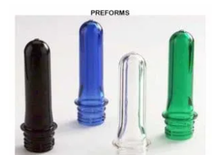
In the blow molding process, the preforms are heated above their glass transition temperature. Then blown using high-pressure air into bottle using metal blow molds.
Mold is small compared to the extrusion blow molding mold. Thickness cannot control. So, the thickness of the final product is not even. Normally, bottle type disposable products are manufactured by injection blow molding.

06.Rotational molding
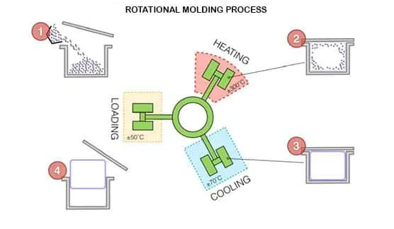
The rotational molding process is used to produce large products such as water tanks. So, it has a large mold.
Before feeding the material into the mold, the required amount of the material is calculated. Only the required amount of the material will feed. (no excess material). Then heat the mold above the melting temperature of the material. While heating, the mold rotates bi-axial. Due to the heat, the material starts to melt and the molten liquid will be coated inside the mold. While rotating the product will cool below the glass transition temperature of the material. So, the product will set in the shape of the mold. After cooling stop the rotation and get the product out by opening the lid. When the product gets out of the mold, it is at a low temperature.
Products with even thickness can be obtained by rotational molding. Thickness is controlled by heat. Because of the even thickness, products are very strong.
There are no any after molding techniques like trimming. And also, zero waste. But this is a very slow process because significant time takes to melt. Because no shear force applies. Cooling also takes a large time. Heat consumption is high because this is an open machine.
07.Calendaring

The calendaring process is used to produce sheet like profiles. Simplest way to produce sheets. The machine contains two co-rotating rollers. The distance between the two rollers decides the thickness of the sheet. The speed of the production is about 100m min-1.
08.Coatings
Coating is the process which coats a liquid on a web.
Roll coating

There are three main rollers use for roll coating. The bottom roller is partially dipped in the coating liquid. When rotating the bottom roller, it is coated with the coating liquid. Due to the rotation action, excess liquid is passed to the second (middle) roller. The web which is going to be coated is passing through the upper two rollers. So, the web is coated while passing through the rollers.
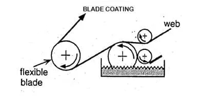
Blade coating
Web passes through two rollers. One roller is partially dipped in the coating liquid. There is a small roller with the contact of the dipped roller. This roller is touched by a small blade which removes the excess material. So, this blade also controls the thickness of the coating on the dipped roller. The web is coated when it passes the dipped roller. Then there is another roller and secondary blade which remove excess material further.
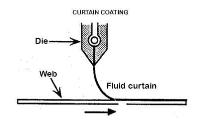
Curtain coating
In curtain coating, web is directly applied coating fluid. To apply the coating, extruder with a slit die is used. The extruder is stationary. Web is passed below the extruder.
09.Spinning
Spinning is the process that produces fibers. There are three different types of spinning processes.
|
Method |
Materials |
|
Melt spinning |
PET |
|
Dry spinning |
PVA |
|
Wet spinning |
PVA, PVC, PAN |
three different types of spinning processes
Melt spinning

There is a spinneret which is pumped melted polymer. When melted material passes through the spinneret, fibers are produced. Polymer is melted and pumped to the spinneret by an extruder. Fibers are coming out from the spinneret. These fibers are quenched by blowing cold are. Then the cooled fibers are accumulated together by a convergence guide. Then the fibers are applied some force by godets. Due to this force, molecules are oriented along the force applied.
Production rate 1-20 m min-1
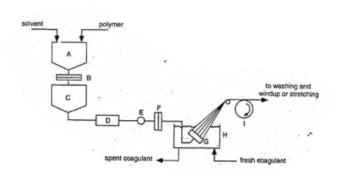
Wet spinning
Materials that are processed by wet spinning can be either polymer solution, polymer dispersion, or a latex. Spinneret is dipped in a coagulant bath. So, when fibers coming out of the spinneret, it will coagulate. The production rate is very low. Because coagulation is a very slow process.
Dry spinning
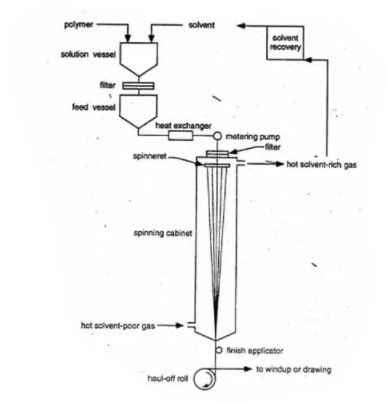
Highly viscous liquid comes out from spinneret. A hot solvent is pumped from the bottom of a spinning cabinet. This hot solvent is removed at the top of the spinning cabinet. Fibers are accumulated at the end of the spinning cabinet. Then it is applied a force to be oriented along the direction of force. Finally, these fibers are wind up.
Dry spinning is the most efficient spinning process. Production rate – 1000m min-1
10.Film blowing

The film blowing process is an extrusion base technique. The die of the extruder produces a tube. This tube is blown and made thin film.
Temperate of the film should be between glass transition temperature Tg and melting temperature Tm of the material. Therefore, it is a rubbery material.
Then the blown tube is clasped by a collapsing board. Clasped thin sheet passes through two rollers. These rollers ate dipped in a cold water bath. So, cooling occurs in the water bath.
Multi-layer sheets can be manufactured by a film blowing process as well as single-layer sheets. As an example, if there is a thin sheet that has three layers of polymers which are (Low-density polyethylene) LDPE, (Linear low-density polyethylene) LLDPE, and (Biaxially oriented polypropylene) BOPP. This sheet can be made by film blowing by using three different extruders which are filled with LDPE, LLDPE, and BOPE separately. In such a process, the LLDPE bubble is blown in the LDPE bubble and the BOPE bubble is blown in the LLDPE bubble.