Piping Isometric Drawings
Piping Isometric drawing is an isometric representation of single pipe line in a plant. It is the most important deliverable of piping engineering department. Piping fabrication work is based on isometric drawings.
Piping isometric drawing consists of three sections. Main Graphic section consist of Isometric Representation of a pipe line route in 3D space, which includes following information :
1. Line number.
2. Flow Direction.
3. Support Tags and location.
4. Piping Components location.
5. Weld Locations.
Section on left or right side of drawing consists of Bill of Material Section for the portion of line shown in isometric graphic. It includes following information for all components :
1. Component Description.
2. Component Material Code.
3. Nominal Size.
4. Quantity.
5. Whether shop material or field material.
6. Number of Spools.
Title bar section at the bottom consists of following information.
1. Project details such as client name, engineering office name, project name, project number, process licensor etc.
2. Pipe line details such as Line Number, Line Size, Insulation, Tracing, Fluid Code, Operating and Design pressure and temperatures, Pressure Testing method such as hydrotest or pneumatic, Test pressure, Piping material class, Inch Dia etc.
Calculations
Inch Meter = Pipe length in Meters X Pipe Size in Inch
Inch Dia = Pipe size in Inch X Number of Joints
Isometric Drawing Checklist
Isometric drawing needs to be checked as per project standard isometric drawing checklist. It includes General Isomtric Check Points as well as Project Specific Check Points.
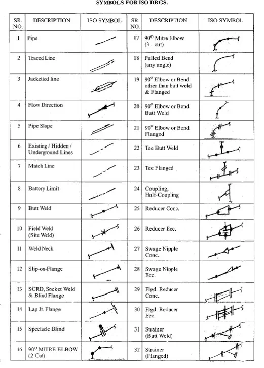
Isometric Drawing Symbols
Project Specific Instructions for Isometrics Checking
Every project has specific requirements. These needs to be reflected in isometrics drawings. Some of these requirements can be regarding following points
1. Pressure Safety Valves
a. Inlet/outlet bolt scope of supply.
b. Outlet bolts and gaskets in which line, inlet or outlet.
2. Fire Fighting lines
1. Spool piece requirements.
2. Flange types (flat face or raised face)
1. Process Vents and Drains
2. Hydrotest vents and drains
3. Flow meters straight run requirements
4. Insulation thickness and scope
5. Valves selection / Tagging
6. Jackscrew flange requirements
7. Hold identification
8. Union / Coupling requirements
9. Galvanized lines spool sizes
10. Dyke Penetration markup
11. Support markup notes
12. Orifice flange orientation / typical sketch
13. PID Tapping sequence markp
14. Flange / gaskets and bolts at iso sheet end
15. Sheet break philosophy.