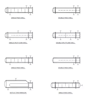
Heat Exchanger Piping
Shell & Tub
After all the required information has been collected for the piping design of a heat exchanger, the first step is to outline clearance and working space in front and around both ends of the exchanger. These working spaces should be kept clear of any piping and accessories to facilitate channel, shell-cover and tube-bundle removal as well as maintenance and cleaning.
The free space at the side of horizontal shell can be used for placement of control stations.
The piping is elevated from grade to have a clearance of 300mm above the grade level. The pipingconnected to channel head nozzles should be furnished with break flanges to facilitate theremoval of the channel head.
Steam lines connecting to a header in the yard
can be arranged on either side of the exchanger centerline without increasing the
pipe length.
Cooling-water lines, if under ground, should run right under the lined-up
channel nozzles of all coolers.
Access to valve hand wheels and instruments will influence the piping arrangement around heat exchangers. Valve handwheels should be accessible from grade and from a convenient accessway. These accessways should be used for arranging manifolds, control valves and instruments.
Plate & Spiral Exchangers
Piping at spiral and plate exchangers is also arranged to allow opening of covers and removal of plates.
Controls at the spiral exchanger are located on the ends of the unit, clear of the cover plate swing area, piping attachment to cover plate nozzles of spiral exchanger will have break flanges.
Controls for plate exchanger are located at the front and one side of the exchanger. The piping is elevated to have clearance from grade as well as convenience for operation of valves.
AIR COOLERS
Piping for air coolers are not routed over tube banks or fans and should be kept clear of the designated space for motor maintenance.
Following Figure Show Location And Piping Arrangement.


