Piping Layout: Tank Farm Piping And General Arrangement Drawing Part-2
Pump Location In Tankfarm
To determine the optimum location of pumps, the potential hazards and client preference shall be considered.
Fig. illustrates the location of pump within the dyke area with the curb wall height of approx. 400-500mm.
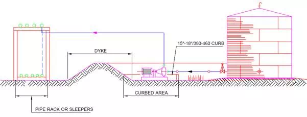
This design protects the pump from minor spillage within the dyke and enable the discharge piping to exit the dyke over the wall and there is no need to have dyke penetration seals.
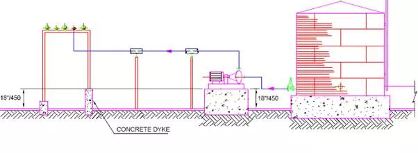
The piping outside the dyke may run on a piperack or sleepers.The pumps located outside the dyke area are illustrated in Fig.
Tank outlet piping can either penetrate the dyke or pass over the dyke in case the minimum liquid level in the tank do cause cavitation in the pump.
Adequate maintenance area around the pump shall be the prime consideration for planning the piping arrangement at suction as well as discharge.
PIPING ARRANGEMENT
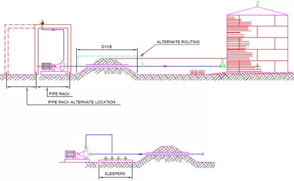
The Optimum piping arrangement in a tankfarm is the most direct route between two points allowing for normal line expansion and stresses.
Fig. illustrates between tanks and pumps.
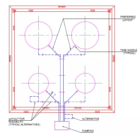
Fig. shows how to accommodate line expansion between tank nozzles and a manifold header. Expansion loops may be added at the sleeper level.
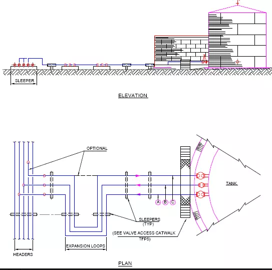
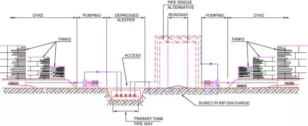
Fig. illustrates a cross-section of piping, pumps, dykes and a primary pipeway in a typical tankfarm.
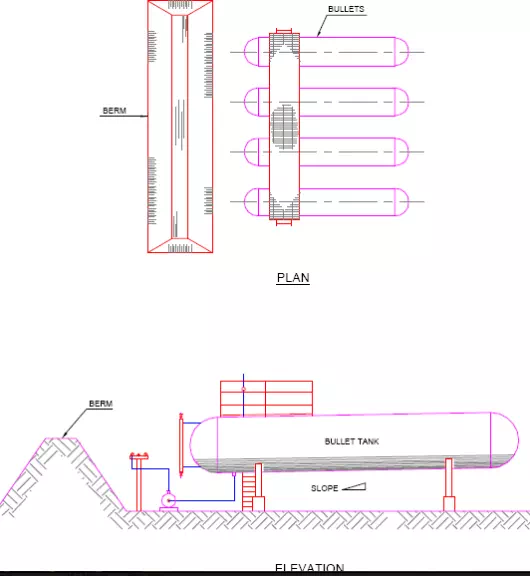
A bullet tank piping arrangement is shown in Fig.
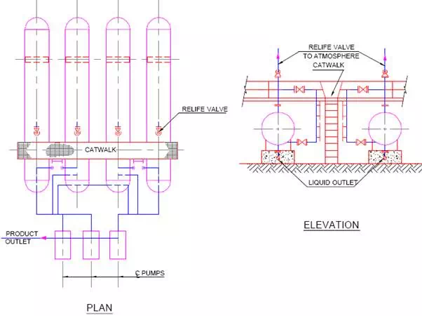
Tanks are installed at the lowest possible elevation to satisfy the pump head requirements. A catwalk is usually located across all the tanks in a row to provide access to the operating valves and instruments. Liquid outlet piping to the suction of Pump shall allow for differential settlement and the flexibility of the piping.
A typical layout of liquefied natural gas (LNG) tanks is shown in Fig.
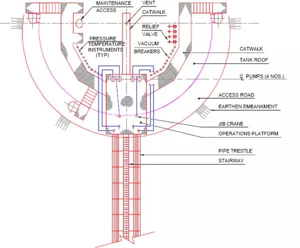
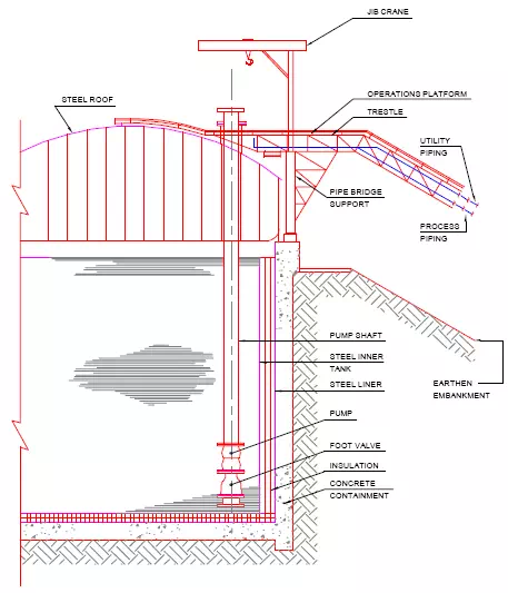
The secondary containment is a steel lined concrete structure. There is heavy cryogenic insulation between primary and secondary containers. Submersible pumps are located at the bottom of the pump shaft. The roof is steel and domed. The operation platform, piping and jib crane structure are supported on the concrete containment wall.
In addition to the provisions for mobile fire-fighting equipment, permanent hydrants, monitors are used for protection against fire in the tankfarm areas.
The codes, regulations viz.CCE, TAC, NFPA shall be consulted to finalise the safety requirement of the tankfarm.
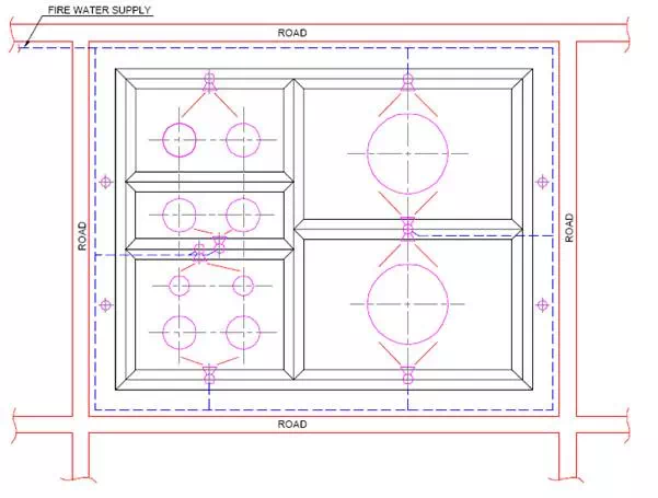
Fig. shows a typical arrangement of firewater hydrants and monitors in a tankfarm. The fire water piping around the tankfarm area shall be provided with supply from two different sources. This is normally done by installation of an firewater pump with diesel engine drive in addition to the electric motor driven pumps.
When high pressure bullet tanks are located close to the process unit, a protection berm is normally used. The berm length shall be slightly longer than the width of the tank area and the berm height will be equal to the height of tanks. These berms are provisions for protection against explosion.
The sump and sump pump shall be provided for disposal of water accumulation due to rain or firefighting. The foam piping shall be arranged with the quick-coupling to the line supply to the foam chamber at the edge of the roof of the tank. The coupling shall be located outside the dyke wall.