Support Details Generally Used :
Following are the type of supports generally used in a project.
SHOE TYPE SUPPORT :
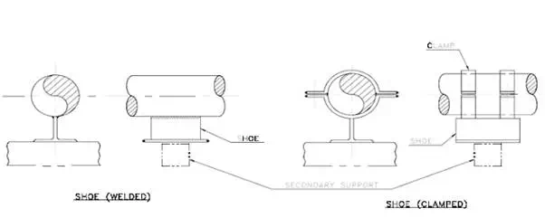
Shoe type support are the supports used maximum in any project. These can be directly welded to pipe orcan be welded to a clamp put around pipe. Shoe type supports are used for supporting lines with insulations.
Basically the detail is as follows :
Basically it is used as a Loose support. With slight addition of details it can be also used as a guide, fixpoint, anchor, transverse guide, limit stops. It can also be modified to be used as Adjustable supports.
These are primary supports and will be supported on secondary supports (i.e. Foundation or structure)
TRUNNION SUPPORTS :
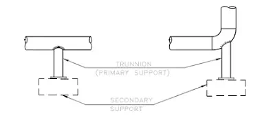
In this type of support, a dummy pipe is welded to the main line so that the dummy pipe becomes a rigidpart of the main pipe line. Now this pipe is suitably supported on a secondary support (Foundation or astructure) The basic detail is as follows :
As per piping requirement, the TRUNNIONS can be VERTICLE (as shown in FIG-9) or can also be in HORIZONTAL. These are used for loose supports, guides, transverse guides, fix points, anchors as well as adjustable supports.
HANGER SUPPORT :
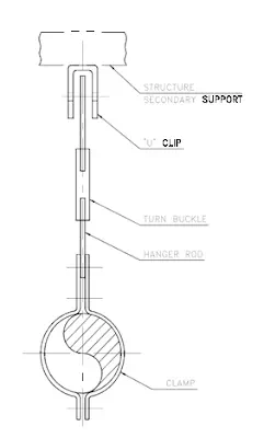
As the name suggest, in a hanger suport the pipe is hung from an structure using a hanger rod.
As is clear from the FIG.-10, pipe can move in all direction except downwards. A hanger support generallyuses a clamp on the pipe. When a turn buckle is used than the support is adjustable type.
Hanger rods are used as a loose supports, which is free to lift up.
SPRING SUPPORT :
Spring Support is a special type of support which is used in the situations where the support point on thepipe is expected to move up or down during the operating condition (due to thermal growth ) from itsinstalled position without spring, the pipe will therefore either lift from secondary support or will make anunsuccessful attempt to press against the rigid secondary support. Both are detrimental to the structuralintegrity of the Piping System.
The spring support basically employs a spring element, which can get compressed or open updepending upon the thermal movement at the support point of pipe. By doing so it takes the vertical load of the piping under both the situations. From the utility point, spring supports are classified as Variable spring type & constant spring type. As per arrangement spring support can be classified as supporting the pipe from under (i.e resting type) or as supporting the pipe from above (i.e. hanger type).
VARIABLE SPRING SUPPORT :
This basically consists of spring which can get compressed or expanded according to thermalexpansion. However this movement causes increase or decrease in supporting force depending on its stiffness and this differential load is transferred to the pipe, but this is much less than that would be with rigid support or rigid hanger.
HANGER TYPE (VARIABLE)
In hanger type variable spring support, the pipe is hung from the secondary support using hanger typespring, as shown.
CONSTANT SPRING SUPPORTS :
In variable spring support variability factor is maintained generally within 25%. When the verticalmovement of support point is large and/or a very less magnitude of differential force from cold tohot condition is permissible, then constant type of support is used. This is also basically spring support butload is supported by it through a lever mechanism in such a way that when spring gets compressedeffective leverage is reduced and vice-versa. So that net supporting force remains constant, i.e. without anyload fluctuation.
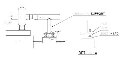
ADJUSTABLE SUPPORT :
As the name suggest, this type of support is capable of adjustment at site to accommodate erectiontolerances of piping. Basically all type of support can be easily modified and made adjustable. A typical example for support at pump suction is shown below.
U-BOLT TYPE SUPPORT :
U-bolt type support is one of the most simplest and extensively used primary support item for supportingun- insulated piping.
These are generally used as GUIDES. These can be used conveniently as fix points for smaller size,non- insulated piping. For large dia pipes, its use as fix point is generally avoided.
SPECIAL SUPPORTING CASES
Few special supporting cases near pumps, tall vessels and exchangers are described as follows :
1.To avoid loading of suction nozzle due to control valve weight, which is nearby, if we provide atrunnion (non-insulated as per
normal practice) to take weight of control valve, then during operation such
nozzle will move up and lift the trunnion off its base. This will load the nozzle and purpose of trunnionwill not get served.
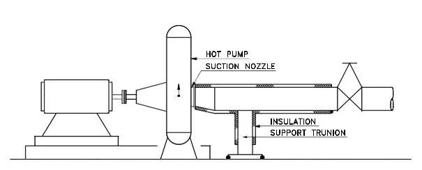
2.This can be avoided by insulating trunnion, so that it will remain hot and will expand upwards and willprovide resting. Thus in most cases, the nozzle loading can be controlled without use of spring supports,near pump nozzles.
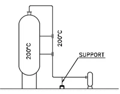
3.When supporting a line coming from top nozzle of a short vessel as shown in ,
if the temperature andmaterial of the vessel and pipe line is same, then the line may be supported at ground level.
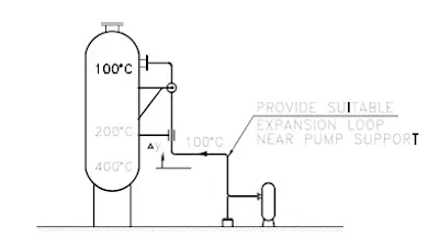
When supporting a line coming from a tall vessel and the line temperature is different from vessel, itshould be supported from vessel at the neutral point with respect to vessel. Such point is normally near thenozzle itself The pump should be connected through flexible loop connection to avoid nozzle loading.
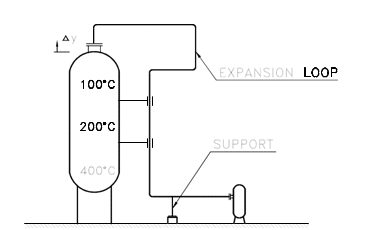
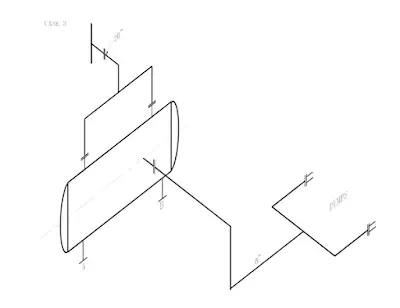
Alternatively line may be supported at bottom (near pump) and loop may be provided at top as shownin FIG.
4.While supporting suction and discharge piping to a pump, the supports being provided should be sufficient to take care the maintenance requirements of the pumps i.e. if the valves / strainers, on the pumps are taken out for maintenance, the lines should remain supported.
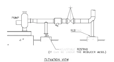
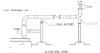
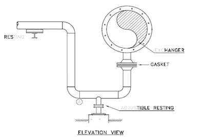
5. In comparatively larger size pipes when a resting support is required at location "A", then an adjustabletype supports should be provided. This is necessary due to the maintenance requirements - such as changing of gaskets, etc.
FIXED SADDLE LOCATION FOR EXCHANGERS
A horizontal equipment will normally have two supports, saddle type. Normally
one of them is made fixedand the
other sliding type.Enclosed sketch showing a few typical cases will make the concept clear.
1.For the long vessel as shown in figure 28, selection of fixed saddle is
decided by stiff connection 'A'. Nowif pumps are located at 'B' then expansion of 15mm (vessel expansion) and 5mm (pump line expansion)i.e. total 20mm will load the pump nozzle excessively.
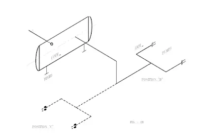
If pumps are located at 'C' then expansion of the pump line will nullify the vessel expansion, since both arein the same direction hence this type of arrangement should be preferred if possible.
2.In such case if saddle 'A' is fixed in figure 29, total expansion of 13m will be required to be absorbedby pipe line.
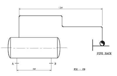
If saddle 'B' is fixed then vessel expansion of 4m will be nullified by pipeline expansion of 4m andonly differential expansion of 9 m will be required to be absorbed.
3.In such case by looking at line size in
figure 30, one may think that more attention be given to 20"connection. But looking correctly, saddle selection
does not make any difference as both are at equaldistance from 20" pipe line. Then selection
should be based in favour of 8" pump line i.e. saddle 'B' shouldbe fixed to reduce load on the pump.
Where ever it is possible to make a flexible piping to the pump, then in such situations, it is possible tomake both the saddles, SLIDING type.
In conclusion fixed saddle should be so chosen that expansion of vessel towards sliding saddle tendsto nullify or substantially reduce differential expansion passed onto connected pipe line. Fixed saddle should
be close to stiff piping connections to the equipment.