Pipe Supports
The Piping Profile in general can be considered as a complex and rigid piping network consisting of various piping components, which have different diameters and weights. At the same time the above network is also subjected to temperature change.
A satisfactory design of the Piping System should therefore give a careful consideration to achieve theabove requirement. This is generally accomplished
by providing external attachments (known as pipe supports) at various locations of the
piping profile.
Purpose Of Pipe Supports
TO SUPPORT WEIGHT OF PIPE-DURING OPERATION & TESTING
Supports are required to support the line during all conditions i.e. during operation as well as during testing.
In case of vapour line this difference will be very large due to hydro testing.Supports should be designed for this load.
Some times line is capable of having longer span but load coming on the support may be verylarge (especially with large
dia pipe lines). Then to distribute the load uniformly, more number of
supportsshould be provided with smaller span.
TO TAKE 'EXPANSION LOAD'
Whenever thermal expansion is restricted by support, it introduces additional load on the support. Supportmust be designed to take this load in addition to all other loads.
TO TAKE 'WIND LOAD'
Wind introduces lateral load on the line. This load is considerable especially
on large diameter pipe. Thistends
to sway the line from its normal position and line must be supported guided
against it. In case of largediameter
overhead lines, supported by tall support extended from floor, wind load
introduces large bendingmoment
and should be considered critically.
TO TAKE 'EARTH QUAKE LOAD'
The earthquake is normally associated with horizontal acceleration of the order of 1 to 3m/sec2. This is around 10% to 30% of the gravitational acceleration and introduces horizontal force of about 10 to 30% of the vertical load (or supported mass). While designing support this should be taken care.
TO ABSORB 'VIBRATION OF PIPING SYSTEM'
When the pipe is subjected to moving machinery or pulsating flow or
very high velocity flow,
pipe maystart vibrating vigorously and ultimately may fail, particularly
if span is large. To avoid this it may be required to introduce additional supports at smaller span
apart from other requirements. It may not take axial load, but must control lateral movements.
TO HAVE 'NOISE CONTROL
In most of the plants, noise is resulting from vibration and if such vibrations
are controlled, noise is reduced
to great extent. In such lines, between clamp (i.e. support) and pipe, asbestos
cloth is put to absorb vibration
and avoid noise.
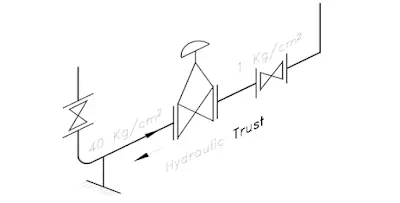
TO TAKE 'HYDRAULIC THRUST IN PIPING
The hydraulic thrust in the pipeline is present at certain point such as pressure reducing valve, reliefvalve, bellows etc.
If the control valve has large pressure differential and line size is more, then this force can be very high.The support should be provided and designed to take this load, otherwise this will load the piping systemand may cause failure.
TO SUPPORT THE SYSTEM DURING 'TRANSIENT PERIOD OF PLANT AND STANDBYCONDITION
Transient condition refers to the start-up or shutdown condition in which one equipment may get heated upfaster and other one get heated slower. Due to this the expansion of one equipment which in normaloperation will get nullified, may not get nullified and exert thermal load on supports.
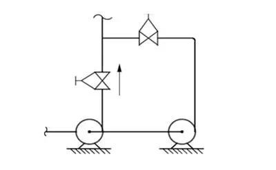
Standby condition is also similar. If there are two pumps, one being standby and both connected in parallel(as shown), design and operating temp. of both the connections will be same. But the expansion of twoparallel legs will not be nullified because at a time only one leg will be hot and another being cold.
TO SUPPORT THE SYSTEM DURING 'MAINTENANCE CONDITIONS'
When for maintenance certain equipment or component like valve is taken out, remaining system shouldnot be left out unsupported.
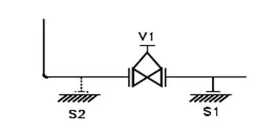
Referring to the FIG, support 'S1' will be sufficient but when valve 'V1' is taken out for maintenance there will not be any support for vertical leg. Therefore second support 'S2' may be required to take care of such condition.
TO SUPPORT THE SYSTEM DURING 'SHUTDOWN CONDITIONS
In shutdown condition all equipment may not be in the same condition as in operating condition.
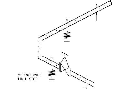
For example, refer the pump discharge line in FIG, Point A is resting, Point B & C are spring supports andPoint D is the pump discharge nozzle. The springs are, designed based on weights considering theweight of fluid as well as pipeline and thermal movements. But during shutdown condition the fluid maybe drained and the pipe becomes lighter. Hence the spring will give upward reaction and shall load thenozzle 'D' beyond permissible limit.
TO SUPPORT THE SYSTEM FOR ERECTION CONDITIONS
Erection condition can be different than the operating condition which should be considered while designing supports.
Erection condition can be different than the operating condition which should be considered while designing supports.
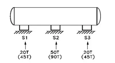
For example for normal operation a long vessel supported by three supports, S1, S2 & S3 is shown inFIG-5. If support S2 is higher, than all load will act at S2 only. During erection if level of S2 is lower thenentire load will be divided into two supports S1, S2 only. Therefore foundation of S1, S2 & S3 shouldbe capable of taking such conditions.
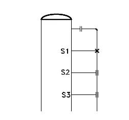
A pipe line supported by S1, S2 & S3 taken from vessel is shown in above FIG - 6. During operation ther
will be no weight at S2 & S3 (as it is only guide), but wind condition will be there.
ads due to such conditions must be considered while designing the supports.