Piping Layout: Piperack Piping Arrangement Drawing Part-2
Yard Piping Arrangement
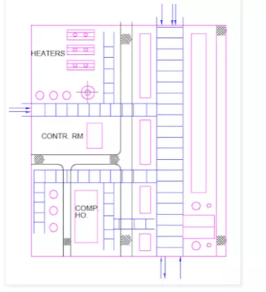
The plant layout determines the main-yard piping runs. Refer sketch, which shows typical piperack layouts for various plant arrangements.
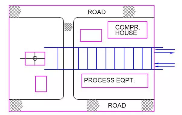
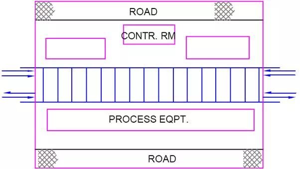

Smaller plants usually have the simplest yard piping as shown in sketch No.. In Fig., the process and utility lines enter and leave at the same end of the plot and Fig., presents a frequently adopted layout, with utility lines entering at one end and process lines at the opposite end.
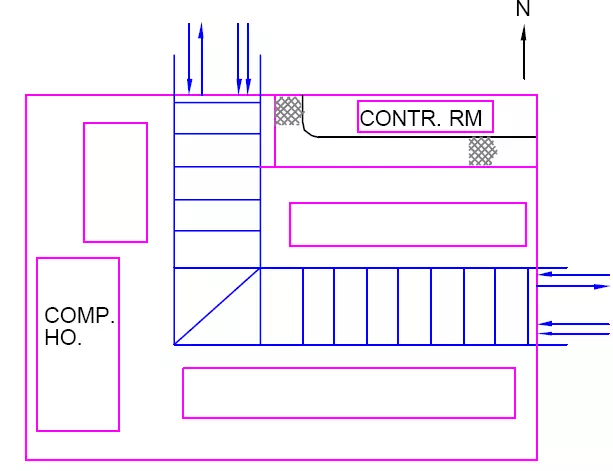
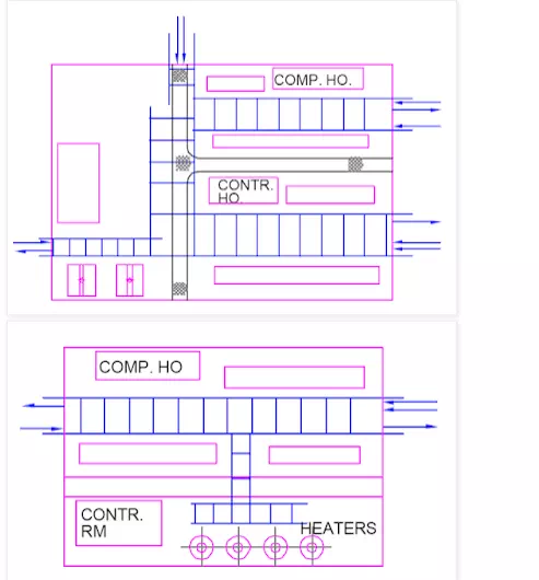
In larger plants, yard piping becomes more complicated as shown in sketch. The piperack arrangement results from an overall plant arrangement, site conditions, client's requirements and plant economy.
Pipelines in the piperack are classified as process lines, relief-line headers and utility headers.
Process lines :
Process lines are those
(a) which interconnect nozzles on process equipment more than 20ft. apart (closer process equipment can be directly interconnected with pipelines)
(b) Product lines which run from vessels, exchangers, or more often from pumps to the unit limits to storage or header arrangement outside the plant.
(c) Crude or other charge lines which enter the unit and usually run in the yard before connecting to exchangers, furnaces or other process equipment e.g. holding drums or booster pumps.
Relief-line headers
Individual relief lines blow down lines and flare lines should be self-draining from all relief valve outlets to knock-out drum, flare stack or to a point at the plant limit. A pocketed relief line system is more expensive, because usually an extra condensate pot is required with instruments, valves and pumps. To eliminate pockets some relief line headers must be placed at higher elevation above the main yard usually on a tee support on the extended piperack column. However, on some noncondensing gas systems self-drainage is not so essential. Relief lines can be individual, some with large diameters and occasionally high temperatures.
Utility lines
Utility lines in the piperack can be put in two groups :
(a) Utility headers serving equipment in the whole plant. Such lines are : low and high pressure steam lines, steam condensate, plant air and instrument air lines. If required, cooling water supply and return and service water can also be arranged on the piperack.
(b) Utility lines serving individually one or two equipment items or a group of similar equipment (furnaces, compressors) in the plant. Such lines are : boiler feedwater, smothering steam, compressor starting air, various fuel oil lines, lubricating oil, cooling oil, fuel gas, inert gas and chemical treating lines.
Steam header should drain to the steam separator for more effective condensate collection. Branch connections to steam headers usually connect to the top to avoid condensate drainage to equipment.
Instrument lines and Electrical cables
Instrument lines and Electrical cables are often supported in the yard and extra space should be provided for these facilities. The best instrument line arrangement eleminates almost all elevation changes between the plant and the control room. This can be easily achieved when instrument lines are supported outside the piperack column on a suitable elevation.