Nozzle Location:
The following information is required to position the drumnozzles.
· Process vessel Sketch
· Instrument vessel sketch
· Piping and Instrumentation diagrams Plant layout guidelines
· Nozzle schedule or summary Insulation requirements
· Unit Plot Plans
The preferred location for level instrument is away from the turbulence at the liquid outlet nozzle.Instrument nozzles shall be located in the quiet zone of the vessel ie. on the opposite side ofthe weir or baffle or near the vapour outlet.
Process nozzles should be located at minimum from the tangent line.
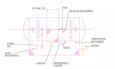
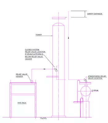
The relief valve should be placed at a point on the top of the drum where the access platform can also provide access to other valves connected to the top of the drum.
The pressure connection should be placed in the vapour space at the top of the drum, so that the face of the pressure gauge is visible from the ground or platform.
The temperature connection is usually close to the bottom outlet, pointing towards the access aisle or platform.
Manholes can be positioned at the top, at the side or at one end of the vessel.
Steam-out connections should be located at the end opposite to the maintenance accesswith additional vent in the bottom section of the drum as steam has a lower molecular weight.
The vent connection should be located in the top section of the drum at the end opposite thesteam out connection.
The drain should be located in the bottom section of the drum.
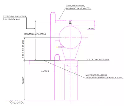
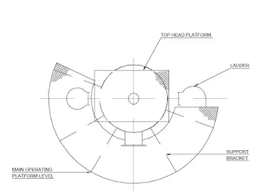
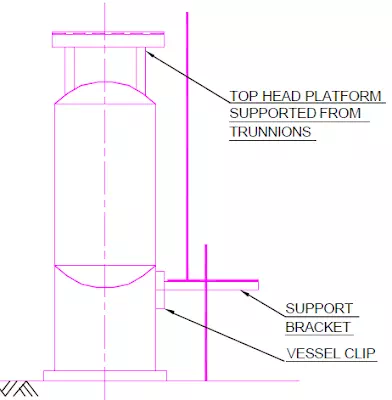
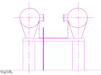
PLATFORM ARRANGEMENTS
A platform with good guard railings is necessary for access if the manhole is more than 3.5m above grade.
Platforms on drums are required for access to valves, instruments, blinds and maintenance accesses.
Platforming should be kept to the minimum necessary to provide safe and suitable accessto manholes and operating valves.
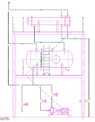
PIPING ARRANGEMENTS
Piping for process drums should be arranged in conjunction with nozzle locations, platform arrangements and the drums location to related equipment.
Piping should be positioned to facilitate the installation of supports with sufficient flexibilityto absorb any excessive stresses during operation.
Relief valves open to atmosphere on low elevated horizontal or vertical drums should bepositioned to allow the discharge piping to be routed to a convenient and safe location. Closed system relief valve should be located at a convenient platform adjacent to the drum abovethe relief valve header.
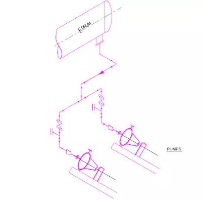
Normally, the liquid or vapour inlet is at the top and at one end of drum with liquid outlet onthe bottom and vapour outlet at the top at opposite end.
Drain and vent lines may be located centrally or at the ends if the drum is horizontal and ifdesired, the drain valve may be placed at the low point of the outlet piping.
Horizontal drums should always have small slopes towards the drain points.
Level, pressure and temperature instruments are used to control the operation of the drumand should be in a position for optimum operation and maintenance.
Level controllers, switches and gauges are either located individually or grouped from a common bridle or stand pipe. The controller must be operable from grade or a platform, switches, gauges and pressure / temperature connections may be operable from a ladder if no platform is available at the required elevation.
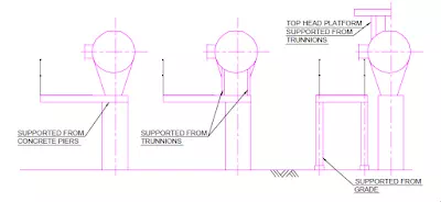
The fixed saddle shall be on the same side of the vessel as the pump suction nozzle. In caseof requirement of an emergency isolation valves, these valves shall be located directly on the vessel nozzle. The position of the support shall allow for the installation of the valve and its actuator.
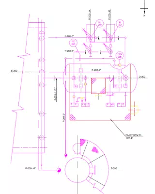
In order to gain access for maintenance and operations purpose, level transmitter (LT) andLevel indicator (LT) nozzles shall be arranged on either side of the access ladder with theircentres 400mm from the ladder centerline.
All instruments shall be grouped on vessels and drums such that the minimum number of ladders and platforms is required, without any compromise on accessibility.