Piping Layout: Compressor Piping And General Arrangement Drawing
Compressors are normally located inside a permanent shelter or building (Compressor House)for weather protection. The compressor house can be fully covered by side cladding to grade level if handling non-hazardous materials e.g. air.
For compressor, handling flammable materials, ventilation and weather protection is assuredby significant openings upto 2.5m ht. at grade level together with roof ventilators.
Except for lighter than air gases, trenches, pits and similar gas traps should be avoided withingas Compressor House. This will eliminate chances of suffocation or explosion risk due toaccumulation of heavy gases in pits.
For open compressor house, the side cladding on all sides should be provided upto 1m belowcrane level.
The general arrangement of compressor house shall consider the vendor drawings andvendor recommendation, if any, for space and location of auxiliary units.
For compressor house where a number of installations from multiple vendors are to beaccommodated, a thorough discussion should be held among the engineers of Piping, Processand Civil discipline to finalize the detail plot plan of the unit.
The clear space between compressors shall be minimum 1.5m or half width of thecompressors. The clearance between rows of compressor and at the end of eachcompressor shall be also 1.5m.Built-in maintenance equipment viz. travelling gantry with overhead crane / monorail with hoist and chain-pulley blocks as well as the drop-out areas shallbe provided in the compressor house.
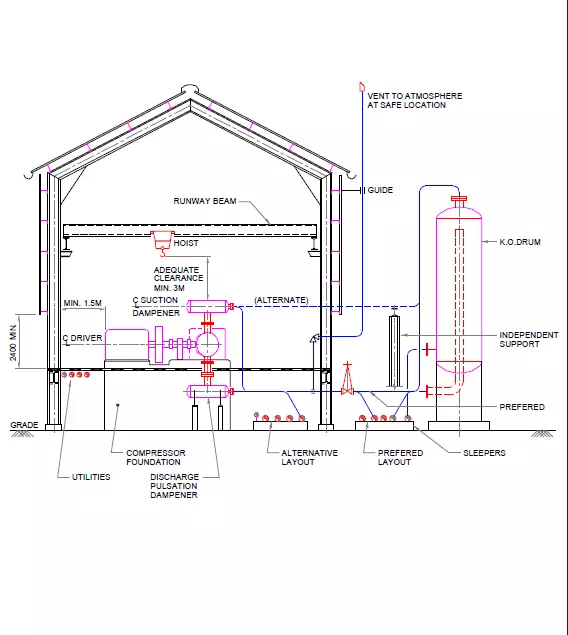
The clearance above the compressor should be at least 3m more than the longest internal partto be removed.
The substantial space required for lube oil and seal oil consoles shall be taken intoconsideration to prepare unit plot plan.
Reciprocating Compressors
Reciprocating compressor generates considerable vibrations due to unbalanced forces, pulsation etc. For this reason, the reciprocating compressors should be located as close as possible to the grade level.
The building foundation and the compressor foundation should be separate to avoid transmission of vibrations from compressor to the building structure.
The pulsation dampeners are used to eliminate pulsation in suction and discharge pipingand to separate the source of vibration from the piping system
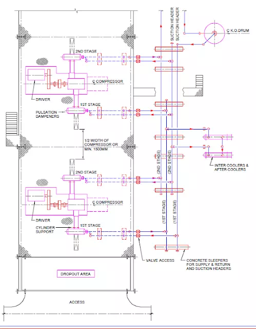
The piping arrangement around the reciprocating compressor should be planned at grade levelfor ease of supporting with minimum changes in direction
The grade supports should be spaced unevenly to reduce harmonic motion in the piping.
The piping routed simply with short run is less prone to vibration, but at the same time theline should be checked for the flexibility and the compressor nozzle loadings within the allowable limits furnished by the vendor.
The piping shall remain clear of the cylinders and the withdrawal space at cylinder heads.
Centrifugal Compressors
The general considerations for centrifugal compressor layout is same as the reciprocating compressor, exception being that for centrifugal compressor, the pipeline size is larger, temperatures can often be higher and nozzle loadings on compressor casing is lower.
The knockout pots inter stage exchangers can be located at grade outside the compressor house with auxiliary equipment consisting of lubricating, seal and control oil systems be placed adjacent to the machine.
The centrifugal compressor inside a building normally have foundations separate from the building foundation.
The centrifugal compressor with drive is generally mounted on the concrete table supported on RCC column.
The maintenance facilities like overhead crane or monorail at the centre of the compressorbay and the drop-out area at one of the building or shed is the usual practice.
If the building is having installation of several compressors, the height of the travelling crane isto be carefully estimated so the machine components and rotors can be lifted over theadjacent equipment.
The compressor suction lines must be free of any foreign particles that could damage theinternals of the machine. Strainers are installed in the inlet line between the isolationvalve and the compressor inlet nozzle.
ASME PTC code recommends a minimum 3 times diameter of straight run piping between elbow and the inlet nozzle.
The designer shall ensure that all connections shown on the vendor piping andinstrumentation diagrams are properly taken care in the piping layout. All valves shall be arranged in such a way that they are accessible from the operating floor around the machine.