Horizontal Centrifugal Pump
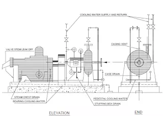
A typical horizontal centrifugal pump suction and discharge piping arrangements is illustrated.
Pump suction piping shall be as short as possible and shall be arranged so that vapourpockets are avoided.
Reducers immediately connected to the pump suction shall be eccentric type flat side up to avoid accummulation of gas pocket.
For end suction pumps, elbows shall not be directly connected to the suction flange. Astraight piece 3 times the line size shall have to be provided at the suction nozzle. This isillustrated.
The effect of elbow directly on suction is illustrated.
For top suction, pump elbow shall not be directly connected to suction flange. A straight piece of minimum 5 times the nozzle size shall have to be provided at the suction nozzle.
T-type strainers are to be used for permanent as well as temporary to avoid disassembly of suction piping for strainer cleaning.
Piping shall be so arranged that forces and moments imposed on the pump nozzles do notexceed the allowable values specified by the vendor.
When a suction vessel operates under vacuum the vent connection of the pump has tobe permanently connected to vapour space of the suction vessel to allow possible filling of the pump with liquid before it is started.
For pumps handling hot fluid, the first factor concerns the support of pump piping whichoften includes large expansion loops for flexibility. When the pumps are located below the pipe rack (to reduce possibility of hydrogen leakage over motor), support becomes easy otherwise the designer should consult stress engineer for best location of stops and hanger. With the optimum
layout and support, it is to be ensured that the loadings on the pumpnozzles are not
ceeded beyond the allowable limits.
Piping configuration for a group of pumps of similar size shall follow identical pattern and thestress analysis of one pump piping should be applicable to the other pumps.
Auxilliary Pump Piping Arrangements :
The auxilliary piping are usually cooling water to mechanical seals, bearings, stuffing boxes,gland quench and lantern rring flush.
When pump fluid is used, a line is attached to the vent connection on the pump case. The circulated seal fluid has to be sent back to pump stream or referred through the seal to pump internal clearances.
In viscous or high temperature hydrocarbon liquids, the seal fluid medium circulates from external source through connections on the pump seal.
Various auxilliary piping plan is recommended in API 610 for proper selection according to design requirements.
Pump vendors usually supply the auxilliary piping and the neat arrangements of these pipingand its support are to be ensured by the designer while reviewing the vendor document.illustrates one typical auxilliary pipig arrangement on the pump base plate.
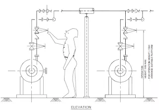
A typical arrangement for piping and valves operation is illustrated with maintenance and operation access.
A typical suction and discharge piping arrangement with common platform for operation of valvesconnected to two adjacent pumps is illustrated.
Suction Basin Of Pump
The basin for the intake of centrifugal pump shall be designed and sized properly forsmooth function of the pump. The recommendations of hydraulic institute is illustrated.
The flow of fluid to the suction bell should be even, smooth and stream lined without any vortices.
A typical sump with the components and relative dimensions of clearance andsubmergence is illustrated.
For multiple pump installations with high capacity pumps, the analysis of a proposed intake design are often made by use of a scale model of the intake basin with all parts such as baffles, screens, gates, separating walls etc.
The large basin is required to ensure low inlet velocity (approx. 2 ft. per sec.) and toeliminate vortexing at the bell mouth.
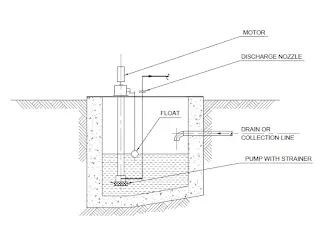
A typical sump pit with pump is illustrated.This sump is the collection pit of waste material coming thru a pipeline. A screen at the mouth of the pump avoids choking / fouling of the pump during operation. The discharge of the pump may go to a slope tank / pond / waste-removal tanker.