Piping layout: Pump Piping And Location
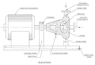
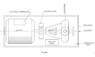
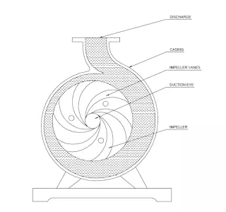
The design of a piping system can have an important effect on the successful operation of a centrifugal pump. Such items as sump design, suction piping design, suction and discharge pipe size and pipe supports must all be carefully considered. A typical horizontal centrifugal pump installation is illustrated.
Selection of the discharge pipe size is primarily a matter of economics. The cost of variouspipe sizes must be compared to the pump size and power cost required to overcome theresulting friction head.
The suction piping size and design is far more important. Many centrifugal pump troubles are caused by poor suction conditions.
The suction pipe should never be smaller than the suction nozzle of the pump and in most cases it should be at least one size larger. Suction pipes should be as short and as straightas possible. Suction pipe velocities should be in the 1.0 - 1.5 metre per second range, unlesssuction conditions are unusually good. Higher velocities will increase the friction loss and can result in trouble some air and vapour separation. This is further complicated when elbows or tees are located adjacent to the pump suction nozzle. In that case uneven flow patterns or vapour separation keeps the liquid from evenly filling the impeller. This upsets hydraulic balance leading to noise, vibration, possible cavitation and excessive shaft deflection. Cavitation, erosion damage, shaft breakage or permature bearing failure etc. may result.
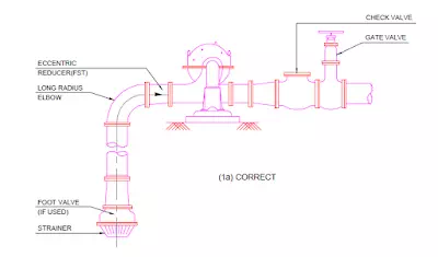
On pump installations involving suction lift, air pockets in the suction line can be a sourceof trouble. The suction pipe should be exactly horizontal or with a uniform slope upwardfrom the sump to the pump as illustrated in There should be no high spots where air cancollect and cause the pump to lose its prime. Eccentric rather than concentric reducers with flat side top should always be used.
If an elbow is required at the suction of a double suction pump, it should be in a vertical position if at all possible. Where it is necessary for some reason to use a horizontal elbow, itshould be a long radius elbow and there should be a minimum of five diameters of straight pipe between elbow and the pump suction as illustrated in
LOCATION
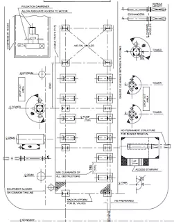
Common location of pumps in chemical and petrochemical plant is under the piperack atgrade. Pumps are to be placed close to and below the vessels from which they take their suction in order to have net-positive suction head (NPSH) required by the pump.
Any reduction in suction line size required at pumps should be made with eccentric reducers,with flat side up to avoid accumulation of vapour pocket. Changes in direction of suction lines should be at least 600mm away from the pump suction.
Pumps should be arranged in line with drivers facing the access gangway. Clearances and pipingshould provide free access to one side of the driver and pump. There must be good access togland / seal and coupling where most of the maintenance and adjustments are done.
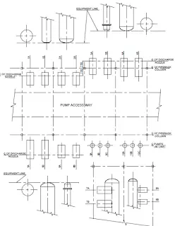
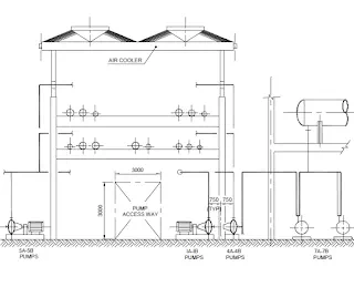
With normal piperack column spacing of 6m, it is generally found that only two pumps ofaverage size can be arranged between the columns, with a preferred clearance of 1m between the pumps. The clearance between any structure / steel work and the pump discharge lineshall be 0.75m minimum. For small pumps upto 18 KW, clearance between pumps should be 0.9m minimum. A space of 2 - 2.5 m should be provided for working aisle.
A typical arrangement of pumps is illustrated.
Means of lifting should be provided for pumps or motor weighing more than 25Kg.
STEPS TO DO PUMP PIPING
Step 1 : Collect the P&ID and the pump data sheet.
Step 2 : Study the pump data sheet and collect the similar (capacity / head) pumpdimensions / nozzle position.
Step 3 : Analyse the location and the space provided in the unit plot plan w.r.t.suction and discharge line routing.
Step 4 : Review the maintenance / operation space around and lifting facility.
Step 5 : Locate the control station, Electrical push button station, Electrical-trench, process fluid drain, flushing / cooling connection as required for the pumpmodel.
Step 6 : Check elevations of all valve handwheels on suction as well as discharge line and provide common platform for valve operation, if required.
Step7 : Make Iso sketch for suction and discharge line with all the items asper P&ID and d
scuss with process engineer for any change.
Step 8 : Finalise supports of the line and issue for stress analysis, if required.
Step 9 : Get the stress analysis report for Nozzle loads. Compare the allowable loads with the actual load for any change & finalisation.
Step 10 : Finalise location of pump / drain or trench / Electrical cable route and issuecivil information to civil for foundation design.
Step 11 : Keep necessary insert plate on the foundation block for support of push button switch, small lines for flushing / cooling manifold.