Piping Layout: Piperack Piping Arrangement Drawing Part-1
The piperack general arrangement is finalised during the development of overall plot plan. The exact width of the piperack, numbers of levels and elevations, the access and maintenance platforms are finalised during piperack piping study.
Normally, the piperack piping study, with its structural and platform requirements is the first priority item for detail engineering of a process unit. The piperack may be an integral part of a process unit located in the middle of the unit or it may be an arterial part connecting several services of other process unit.
The following data and drawings are required to be studied before starting the detailed design of piperack piping study:
Unit Plot Plan / Overall Plot Plan, Piping and Instrumentation diagrams Plant layout specification, Client specification, Material of construction, Fireproofing requirements
STEPS TO PIPERACK PIPING
The first step in the development of any piperack is the generation of a line-routing diagram. A line routing diagram is a schematic representation of all process piping systems drawn on a copy of piperack general arrangement drawing / or on the unit plot plan where the piperack runs in the middle of the process unit.
Based on the information available on the first issue of P&I Diagram / Process flow diagram i.e. line size, line number, pipe material, operating temperature etc. the line routing diagram is to be completed.
Once the routing diagram is complete, the development of rack width, structural column spacing, road crossing span, numbers of levels and their elevations should be started.
Piperack column spacing shall be decided based on the economics of the pipe span as well as the truss arrangement to accommodate double the span for road crossing or avoiding underground obstructions.
Piperack arrangement should be developed to suit the specific plant requirements.
Normally, piperack carry process lines on the lower level or levels and the utility lines on the top level. Instrument and electrical trays are integrated on the utility level if space permits or on a separate level above all pipe levels.
Any piperack design should provide provision for future growth to the extent of 25 to 30% on the rack clear width.
When flanges or flanged valves are required on two adjacent lines, the flanges are to be staggered.
Thermal expansion or contraction must be accomodated by keeping sufficient clearance at the location where the movements will occur.
After analysing all the requirements and arrangements, the dimensions are to be rounded off to the next whole number. Based on the economics, the width and the number levels e.g. two tier of 30 ft. wide or three tier of 20 ft. wide rack will be decided.
The gap between the tiers shall be decided on the basis of the largest diameter pipeline and its branching. The difference between the bottom line of pipe in the rack and the bottom of a branch as it leaves the rack shall be decided carefully, to avoid any interference due to support, insulation, size of branch etc. All branch lines from the main lines on piperack shall be taken aesthetically on a common top of steel (TOS).
LOCATION OF VALVES
Various factors shall be considered while locating each line, valve and instrument in a piperack. In a standard process unit piperack, process lines are located on the lower levels, utility lines are on the next higher level and a separate top level is arranged for electrical and instrument cable trays. The requirements and locations of electrical and instrument cable trays alongwith their spacing, protective cover, approach platform / walkways are to be discussed with the electrical and instrument engineers.
The largest lines should be located near the supporting columns to reduce the overall load on the supporting beams.
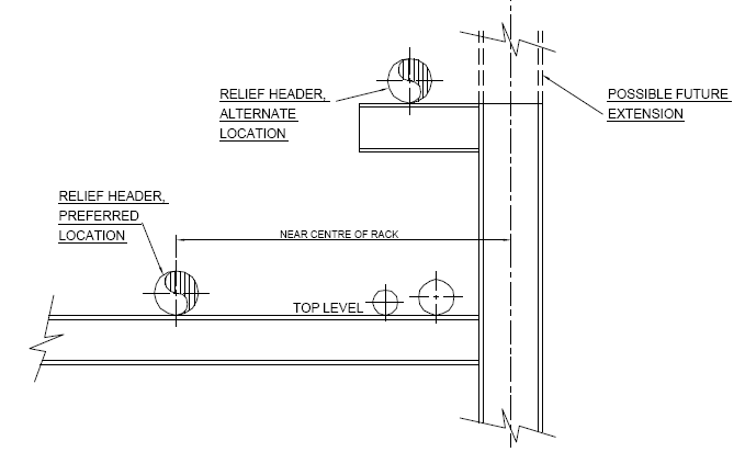
The relief headers must be located above the top level of the rack to allow the line to drain to blowdown drum. The designer should avoid locating pipeline over the centreline of structural column for support so that the columns can be extended for future rack expansion.
Shut-off valves at utility headers are located inside the rack area in the horizontal position directly above the header. Valves must be accessible from platforms or by chain operators (chain to fall free of obstructions hampering operation).
Refer sketch. This view highlights features requiring additional considerations. The width of the access way is determined by the space needed to maintain the equipment located at grade below the piperack.
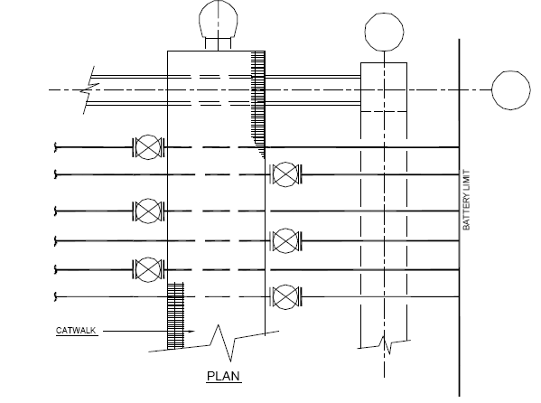
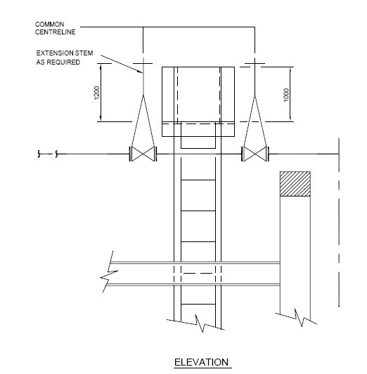
The valves are staggered on either side of the catwalk and handwheel extension stems are
furnished when necessary to facilitate operation.