TWO-PHASE FLOW: EFFECTIVE AND RELATIVE PERMEABILITIES
In describing Darcy's law, it has so far been assumed that the permeability is a rock property which is a constant, irrespective of the nature of the fluid flowing through the pores. This is correct (with the noted exception of gas flow either at low pressures or very high rates) provided that the rock is completely saturated with the fluid in question, and results from defining k in equ. (4.8) as the permeability, rather than the K in equ. (4.3), the latter having a dependence on the fluid properties.
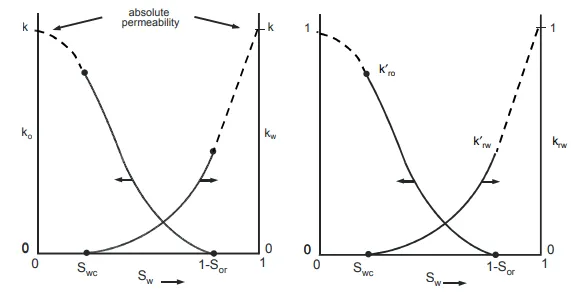
The permeability so defined is termed the absolute permeability. If there are two fluids, such as oil and water, flowing simultaneously through a porous medium, then each fluid has its own, so-called, effective permeability. These permeabilities are dependent on the saturations of each fluid and the sum of the effective permeabilities is always less than the absolute permeability.
The saturation dependence of the effective permeabilities of oil and water is illustrated in fig. 4.8(a). It is conventional to plot both permeabilities as functions of the water saturation alone since the oil saturation is related to the former by the simple relationship So = 1−Sw. Considering the effective permeability curve for water, two points on this curve are known. When Sw = Swc, the connate or irreducible water saturation, the water will not flow and kw = 0. Also, when Sw = 1 the rock is entirely saturated with water and kw = k, the absolute permeability. Similarly for the oil, when Sw = 0 (So = 1) then ko = k and, when the oil saturation decreases to Sor, the residual saturation, there will be no oil flow and ko = 0. In between these limiting values, for both curves, the effective permeability functions assume the typical shapes shown in fig. 4.8(a).
The main influence on the shapes of the curves appears to be the wettability, that is, which fluid preferentially adheres to the rock surface8 . Although it is difficult to quantify this influence, the permeability curves can be measured in laboratory experiments for the wettability conditions prevailing in the reservoir9
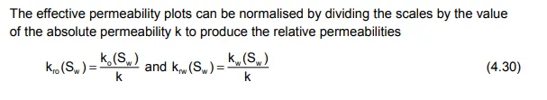
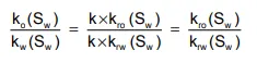
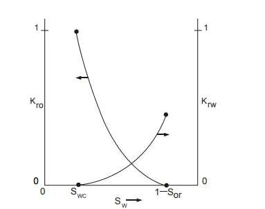
The plots of kro and krw, corresponding to the effective permeability plots of fig. 4.8(a), are drawn in fig. 4.8(b). Both sets of curves have precisely the same shape, the only difference being that the relative permeability scales have the range zero to unity. Relative permeabilities are used as a mathematical convenience since in a great many displacement calculations the ratio of effective permeabilities appears in the equations, which can be simplified as the ratio of
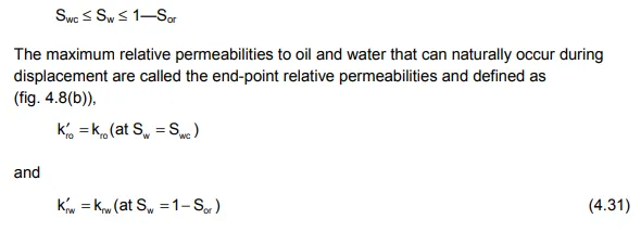
In figs. 4.8(a) and (b) the parts of the curves for water saturations below Sw = Swc and above Sw = 1 - Sor are drawn as dashed lines because, although these sections of the plots can be determined in laboratory experiments, they will never be encountered in fluid displacement in the reservoir, since the practical range of water saturations is
Sometimes the effective permeability curves are normalised in a different manner than described above, by dividing the scales of fig. 4.8(a) by the value of ko (Sw = Swc ) = k ro k′ , the maximum effective permeability to oil. The resulting curves are shown in fig
Relative permeabilities are measured in the laboratory by studying the displacement of oil by water (or gas) in very thin core plugs, in which it is safe to assume that the fluid saturations are uniformly distributed with respect to thickness. Therefore, these laboratory-measured, or rock-relative permeability relationships, can only be used directly to describe flow in a reservoir in which the saturations are also uniformly distributed with respect to thickness. In the majority of practical cases, however, there is a non-uniform water saturation distribution in the vertical direction which is governed by capillary and gravity forces and, therefore, there must also be a relative permeability distribution with respect to thickness. Because of this, the rock-relative permeabilities can seldom be used directly in field displacement calculations.