Fluid Catalytic Cracking (FCC)
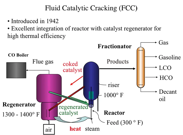
Fluid Catalytic Process, also introduced in 1942, offered an excellent integration of the cracking reactor and the catalyst regenerator that provides the highest thermal efficiency, as shown in Figure 7.7. In FCC, a fluidized-bed (or fluid-bed) of catalyst particles is brought into contact with the gas oil feed along with injected steam at the entrance (called the riser) of the reactor. The hot catalyst particles coming from the regenerator unit evaporate the feed gas oil upon contact in the riser, and the cracking starts as the gas oil vapors and the catalyst particles move upward in the reactor. The temperature of the catalyst particles drops as the evaporation of gas oil and endothermic cracking reactions proceed during the upward movement. Cracking reactions also deposit a significant amount of coke on the catalysts, leading to the deactivation of the catalyst. After removing the adsorbed hydrocarbons by steam stripping, the coked catalyst is sent to the regeneration unit to burn off the coke with air. Heat released from burning the coke deposit increases the temperature of the catalyst particles that are returned to the riser to complete the cycle. Burning off the rejected carbon (coke) in the regenerator provides the energy necessary for cracking without much loss, thus increasing the thermal efficiency of the process. The cracking products are sent to the fractionator for recovery after they are separated from the catalyst particles in the upper section of the reactor [3].
In the reactor, the cracking reactions initiate on the active sites of the catalysts with the formation of carbocations and the subsequent ionic chain reactions produce branched alkanes and aromatic compounds to constitute the crackate (cracked gasoline with high octane number), light olefins, cycle oils, and slurry oil that are sent to the fractionator. A carbon-rich byproduct of catalytic cracking, termed “coke,” deposits on catalyst surfaces and blocks the active sites. FCC is considered a carbon rejection process because the coke deposited on the catalyst surface and eventually burned off for heat is rich in carbon and thus enables the production of large quantities of a light distillate (crackate) in the process without the addition of hydrogen.
Two different configurations of the commercial FCC processes exist depending on the positions of the reactor and the regenerator: they can be side by side or stacked, where the reactor is mounted on top of the regenerator. Major licensor companies that offer FCC processes with different configurations include Kellogg Brown & Root, CB&I Lummus, ExxonMobil Research and Engineering, Shell Global Solutions International, Stone & Webster Engineering Corporation, Institut Francais du Petrole (IFP), and UOP. Figure 7.8 shows examples of Exxon and UOP designs [1,4]. The UOP design of high-efficiency two-stage regenerator units offer advantages of uniform coke burn, higher conversion of CO to CO2 and lower NOx emissions among others. Another modification to FCC plants could be the installation of a catalyst cooler, which may provide better control of the catalyst/oil ratio; the ability to optimize the FCC operating conditions, increase conversions, and process heavier residual feedstocks; and better catalyst activity and catalyst maintenance [3].
In the link below (external link), the animation of an explosion in an FCC unit in 2015 (7:12 minute long) provides a good review of the FCC process, and points out the potential hazards of working with hydrocarbons exposed to high temperatures in refinery units:
Figure 7.7. Process configuration for Fluid Catalytic Cracking (FCC) process.

Figure 7.8. Different configurations of the FCC Units [4].