Casing inspection logs
Casing failure can be caused by:
· Deformation
· Physical wear
· Corrosion
Preventing such failures is critical to maintaining well production.
Casing inspection logs
There are four commonly used techniques for the inspection of casing:
· Cased-hole calipers
· Flux-leakage tools
· Electromagnetic phase-shift tools
· Ultrasonic tools
Ultrasonic radial-cement-evaluation devices and modified openhole-imaging devices are also used to evaluate casing for indications of[1][2][3][4]:
· Potential collapse
· Thinning
· Internal or external metal loss
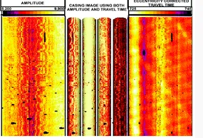
Echo amplitude and travel time provide images of the condition of the inside casing surface (e.g., buildup, defects, and roughness such as pitting and gouges) (Fig. 1), and travel-time and resonant-frequency analysis provide casing thickness (Fig. 2).
·
Fig. 1 – Casing evaluation log display. Holes in the casing are visible in the series of ultrasonic images that are based on amplitude (left) and corrected travel time (right). The center 3D images show the pipe in 90° quadrants. The image shading is generated from the amplitude data[4] (courtesy of SPE).
· 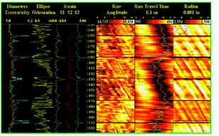
Fig. 2 – Ultrasonic casing-evaluation display. In this example, casing radius and shape are presented as log curves and image maps and deformed casing is easily identified (courtesy of Baker Atlas).
The acoustic caliper generated from the pulse/echo travel time provides the casing inside diameter (an average of all transducers or a single circumferential scan). An estimate of casing ovality is obtained using only the maximum and minimum measurements. Then, if the nominal value of the outside casing diameter is assumed, changes in thickness can be calculated and internal defects identified. Frequency analysis determines the casing resonant frequency from the acoustic waveform; casing thickness is inversely related to the resonant frequency. By combining travel time and resonant-frequency measurements and using data from all available transducers (or a single scan), presentations showing casing cross sections are used to highlight casing damage such as (Fig. 2):
· Thinning
· Corrosion metal loss
· Collapse
Multifinger calipers are used to identify changes in casing diameter as indicators of wear and corrosion. They are also used to monitor casing deformation.[5] They can have up to 80 spring-loaded feelers or fingers, depending on the nominal casing diameter (Fig. 1). Different multifinger caliper tools can log casing sizes from 4 to 20 in. [100 to 500 mm]. Smaller tools are available for tubing inspection. Each hardened finger can measure the internal casing diameter with a radial resolution of a few thousandths of an inch and a vertical resolution of a few hundredths of an inch at a typical logging speed of 1800 ft/hr [550 m/h]. Measurements are taken many times per second for each finger, giving a typical spatial-sampling interval of approximately 0.15 in. [4 mm] as the tool travels up the borehole. A finger extends where it encounters a pit or hole and retracts where there is scale present or there has been partial collapse. A potential disadvantage is that the fingers can damage the casing, although modern electronic tools have a very low finger pressure to avoid this. The tool also indicates which finger is the one on the highest side of the well. Moreover, fingers can be grouped azimuthally. All these data can be combined with the measurements of diameter to produce a 3D picture of the casing, including cross-sectional distortions and changes in the trajectory of the well axis as small as 0.01°. The data can be either transmitted to the surface where the tool is run on a wireline or stored downhole where the tool is deployed on a slickline.
· 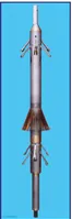
Fig. 1 – Multifingered caliper tool for development as a memory tool on slickline or as a surface-readout tool on monoconductor cable. This tool has 60 fingers, a 4-in. [100-mm] diameter, and a measurement range of 4.4 to 9.625 in. [114 to 245 mm]. It has a radial resolution of 0.005 in. [0.13 mm], a radial accuracy of ± 0.03 in. [0.75 mm], and a vertical resolution of 0.23 in. [5.84 mm] at a logging speed of 3,000 ft/hr [914 m/hr]. Pressure and temperature ratings are 15,000 psi [103 MPa] and 350°F [177°C], respectively. Note the tool centralizers. (Courtesy of Sondex.)
There are two types of multifinger calipers, mechanical and electronic, although the distinction is misleading because all such calipers are mechanical in their deployment. The difference is in the way in which data are recorded. Older calipers were truly mechanical in that they were operated on a slickline and used a scribe chart for downhole data recording. These mechanical calipers have high temperature ratings because they are not limited by the ratings of downhole electronics [e.g., 600°F (315°C) for the Kinley caliper offered by the Expro Group]. Modern tools convert the mechanical data into electronic information for downhole memory storage or for transmittal uphole for real-time data display. Operating temperatures for these electronic tools are typically up to 350°F [177°C].
Multifinger tools contain an inclinometer so that tool deviation and orientation can be recorded. If these brmeters are known, the high-quality output from modern multifinger calipers allows several image-based products to be generated. Deliverables include digital "maps" of the ovality of the casing and its internal diameter. The logs can be run and displayed in time-lapse mode to quantify the rates of corrosion or scale buildup. A digital image of variations in the inner diameter of the casing is the principal tool for identifying corrosion. In its basic form, this is an electronic version of what one might see using a downhole video camera; however, the electronic image can be rotated and inspected from any angle. Artificial colors are used to bring out anomalies.
Another processed product is the 3D shape of downhole tubulars to map the trajectory of the wellbore and to quantify casing deformation. An interesting example of the use of multifinger-caliper data to evaluate casing deformation in primary heavy-oil production in northeastern Alberta has been described by Wagg et al.[6] (Fig. 2). Several postulates for formation movement were modeled and compared with the observed casing deformations. In the end, it was concluded that sand production from an elongated disturbed zone caused reservoir shortening to an extent that could account for the wellbore observations. The use of casing-deformation logs as a tool in reservoir geomechanics leads to an improved knowledge base for well design.
· 
Fig. 2 – Digital image of casing deformation based on multifingered caliper data processed with C-FER Technologies’ CalTran™ software. The “spikes” are indications of casing connections or perforations.[6]
Although they are intended for cased-hole application, it is possible to use multifingered calipers in open hole. The results are much more detailed than with a standard openhole caliper, and the output can be displayed as images similar to those obtainable with ultrasonic imaging tools.