Artificial lift
Production wells are free flowing or lifted. A free-flowing oil well has enough downhole pressure to reach suitable wellhead production pressure and maintain an acceptable well flow. If the formation pressure is too low, and water or gas injection cannot maintain pressure or are not suitable, the well must be artificially lifted. For smaller wells, 0.7 MPa (100 PSI) wellhead pressure with a standing column of liquid in the tubing is measured, by a rule of-thumb method, to allow the well to flow. Larger wells will be equipped with artificial lift to increase production, even at much higher pressures. Some artificial lift methods are:
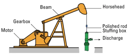
Rod pumps
Sucker rod pumps, also called donkey or beam pumps, are the most common artificial lift system used in land-based operations. A motor drives a reciprocating beam, connected to a polished rod passing into the tubing via a stuffing box. The sucker rod continues down to the oil level and is connected to a plunger with a valve. On each upward stroke, the plunger lifts a volume of oil up and through the wellhead discharge. On the downward stroke it sinks (it should sink, and not be pushed) allowing oil to flow though the valve.
The motor speed and torque is controlled for efficiency and minimal wear with a pump off controller (PoC). Use is limited to shallow reservoirs down to a few hundred meters, and flows up to about 40 liters (10 gallons) per stroke.
ESP
A downhole pump inserts the whole pumping mechanism into the well. In modern installations, an electrical submerged pump (ESP) is inserted into the well. Here, the whole assembly consisting of a long narrow motor and a multiphase pump, such as a progressive cavity pump (PCP) or centrifugal pump, hangs by an electrical cable with tension members down the tubing.
Installations down to 3.7 km with power up to 750 kW have been installed. At these depths and power ratings, medium voltage drives (up to 5kV) must be used. ESPs work in deep reservoirs, but are sensitive to contaminants such as sand, and efficiency is sensitive to gas oil ration (GOR) (where gas over 10% dramatically lowers efficiency.
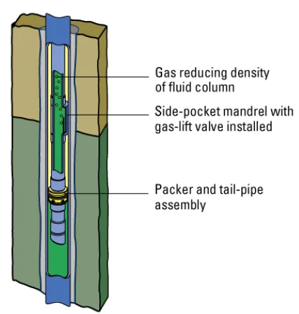
Gas lift
A gas lift injects gas into the well flow. The downhole reservoir pressure to the wellhead falls off, due to the counter pressure from weight of the oil column in the tubing. Thus, a 150 MPa reservoir pressure at 1,600 meters will fall to zero in the wellhead if the specific gravity is 800 kg/m2 (0.8 times water). By injecting gas into this oil, the specific gravity is lowered and the well will start to flow. Typically, gas is injected between the casing and tubing, and a release valve on a gas lift mandrel is inserted into the tubing above the packer.
The valve will open at a set pressure to inject lift gas into the tubing. Several mandrels with valves set at different pressure ranges can be used to improve lifting and startup.
Gas lift can be controlled for a single well to optimize production, and to reduce slugging effects where the gas droplets collect to form large bubbles that can upset production. Gas lift can also be optimized over several wells to use available gas in the most efficient way.
Plunger lift
The plunger lift is normally used on low pressure gas wells with some condensate, oil or water, or high GOR wells. In this case, the well flow conditions can be such that liquid starts to collect downhole and eventually blocks gas so that the well production stops. In this case, a plunger with an open/close valve can be inserted in the tubing. A plunger catcher at the top opens the valve and can hold the plunger, while another mechanism downhole closes the valve.
The cycle starts with the plunger falling into the well with its valve open. Condensed gas and oil can pass though the plunger until it reaches bottom. There the valve is closed, now with a volume of oil, condensate or water on top. Gas pressure starts to accumulate under the plunger and after a time pushes the plunger upwards, with liquid on top, which eventually flows out of the wellhead discharge.
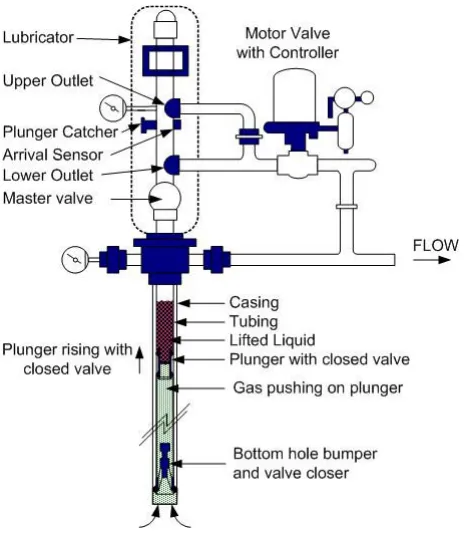
When the plunger reaches the wellhead plunger catcher, the valve opens and allows gas to flow freely for some time while new liquid collects at the bottom. After a preset time, the catcher releases the plunger and the cycle repeats.