Recovery Of Oil And Gas
Primary recovery: natural drive and artificial lift
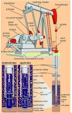
Petroleum reservoirs usually start with a formation pressure high enough to force crude oil into the well and sometimes to the surface through the tubing. However, since production is invariably accompanied by a decline in reservoir pressure, “primary recovery” through natural drive soon comes to an end. In addition, many oil reservoirs enter production with a formation pressure high enough to push the oil into the well but not up to the surface through the tubing. In these cases, some means of “artificial lift” must be installed. The most common installation uses a pump at the bottom of the production tubing that is operated by a motor and a “walking beam” (an arm that rises and falls like a seesaw) on the surface. A string of solid metal “sucker rods” connects the walking beam to the piston of the pump. Another method, called gas lift, uses gas bubbles to lower the density of the oil, allowing the reservoir pressure to push it to the surface. Usually, the gas is injected down the annulus between the casing and the production tubing and through a special valve at the bottom of the tubing. In a third type of artificial lift, produced oil is forced down the well at high pressure to operate a pump at the bottom of the well (see also hydraulic power).
·
·
The “artificial lift” of petroleum with a beam-pumping unit.
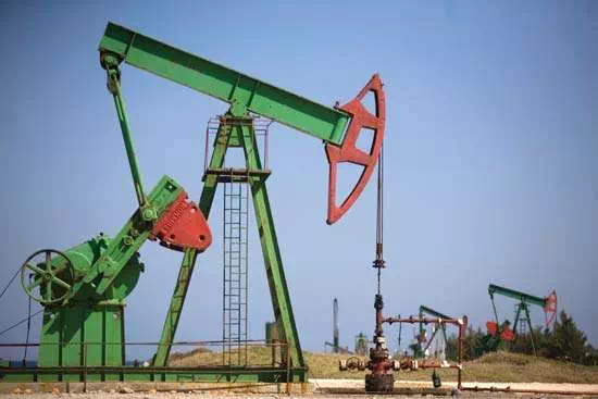
A “walking beam” operating an oil well pump in Brisas del Mar, Cuba.Alexandre Meneghini/AP
With hydraulic lift systems, crude oil or water is taken from a storagetank and fed to the surface pump. The pressurized fluid is distributed to one or more wellheads. For cost-effectiveness, these artificial lift systems are configured to supply multiple wellheads in a pad arrangement, a configuration where several wells are drilled near each other. As the pressurized fluid passes into the wellhead and into the downhold pump, a piston pump engages that pushes the produced oil to the surface. Hydraulic submersible pumps create an advantage for low-volume producing reservoirs and low-pressure systems. Conversely, electrical submersible pumps (ESPs) and downhole oil water separators (DOWS) have improved primary production well life for high-volume wells. ESPs are configured to use centrifugal force to artificially lift oil to the surface from either vertical or horizontal wells. ESPs are useful because they can lift massive volumes of oil. In older fields, as more water is produced, ESPs are preferred for “pumping off” the well to permit maximum oil production. DOWS provide a method to eliminate the water handling and disposal risks associated with primary oil production, by separating oil and gas from produced water at the bottom of the well. Oil and gas are later pumped to the surface while water associated with the process is reinjected into a disposal zone below the surface.
With the artificial lift methods described above, oil may be produced as long as there is enough nearby reservoir pressure to create flow into the well bore. Inevitably, however, a point is reached at which commercial quantities no longer flow into the well. In most cases, less than one-third of the oil originally present can be produced by naturally occurring reservoir pressure alone. In some cases (e.g., where the oil is quite viscous and at shallow depths), primary production is not economically possible at all.
Secondary recovery: injection of gas or water
When a large part of the crude oil in a reservoir cannot be recovered by primary means, a method for supplying extra energy must be found. Most reservoirs have some gas in a miscible state, similar to that of a soda bottled under pressure before the gas bubbles are released when the cap is opened. As the reservoir produces under primary conditions, the solution gas escapes, which lowers the pressure of the reservoir. A “secondary recovery” is required to reenergize or “pressure up” the reservoir. This is accomplished by injecting gas or water into the reservoir to replace produced fluids and thus maintain or increase the reservoir pressure. When gas alone is injected, it is usually put into the top of the reservoir, where petroleum gases normally collect to form a gas cap. Gas injection can be a very effective recovery method in reservoirs where the oil is able to flow freely to the bottom by gravity. When this gravity segregation does not occur, however, other means must be sought. An even more widely practiced secondary recovery method is waterflooding. After being treated to remove any material that might interfere with its movement in the reservoir, water is injected through some of the wells in an oil field. It then moves through the formation, pushing oil toward the remaining production wells. The wells to be used for injecting water are usually located in a pattern that will best push oil toward the production wells. Water injection often increases oil recovery to twice that expected from primary means alone. Some oil reservoirs (the East Texas field, for example) are connected to large, active water reservoirs, or aquifers, in the same formation. In such cases it is necessary only to reinject water into the aquifer in order to help maintain reservoir pressure.
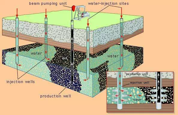
The recovery of petroleum through waterflooding. (Background) Water is pumped into the oil reservoir from several sites around the field; (inset) within the formation, the injected water forces oil toward the production well. Oil and water are pumped to the surface together.From (inset) R. Baker, A Primer of Offshore Operations, 2nd ed., Petroleum Extension Service (PETEX), © 1985 The University of Texas at Austin, all rights reserved; R. Baker, Oil & Gas: The Production Story, Petroleum Extension Service (PETEX), © 1983 The University of Texas at Austin, all rights reserved
Enhanced recovery
Enhanced oil recovery (EOR) is designed to accelerate the production of oil from a well. Waterflooding, injecting water to increase the pressure of the reservoir, is one EOR method. Although waterflooding greatly increases recovery from a particular reservoir, it typically leaves up to one-third of the oil in place. Also, shallow reservoirs containing viscous oil do not respond well to waterflooding. Such difficulties have prompted the industry to seek enhanced methods of recovering crude oil supplies. Since many of these methods are directed toward oil that is left behind by water injection, they are often referred to as “tertiary recovery.”
Miscible methods
One method of enhanced recovery is based on the injection of natural gas either at high enough pressure or containing enough petroleum gases in the vapour phase to make the gas and oil miscible. This method leaves little or no oil behind the driving gas, but the relatively low viscosity of the gas can lead to the bypassing of large areas of oil, especially in reservoirs that are not homogeneous. Another enhanced method is intended to recover oil that is left behind by a waterflood by putting a band of soaplike surfactant material ahead of the water. The surfactant creates a very low surface tension between the injected material and the reservoir oil, thus allowing the rock to be “scrubbed” clean. Often, the water behind the surfactant is made viscous by addition of a polymer in order to prevent the water from breaking through and bypassing the surfactant. Surfactant flooding generally works well in noncarbonate rock, but the surfactant material is expensive and large quantities are required. One method that seems to work in carbonate rock is carbon dioxide-enhanced oil recovery (CO2 EOR), in which carbon dioxide is injected into the rock, either alone or in conjunction with natural gas. CO2 EOR can greatly improve recovery, but very large quantities of carbon dioxide available at a reasonable price are necessary. Most of the successful projects of this type depend on tapping and transporting (by pipeline) carbon dioxide from underground reservoirs.
In CO2 EOR, carbon dioxide is injected into an oil-bearing reservoir under high pressure. Oil production relies on the mixtures of gases and the oil, which are strongly dependent on reservoir temperature, pressure, and oil composition. The two main types of CO2 EOR processes are miscible and immiscible. Miscible CO2 EOR essentially mixes carbon dioxide with the oil, on which the gas acts as a thinning agent, reducing the oil’s viscosity and freeing it from rock pores. The thinned oil is then displaced by another fluid, such as water.
Immiscible CO2 EOR works on reservoirs with low energy, such as heavy or low-gravity oil reservoirs. Introducing the carbon dioxide into the reservoir creates three mechanisms that work together to energize the reservoir to produce oil: viscosity reduction, oil swelling, and dissolved gas drive, where dissolved gas released from the oil expands to push the oil into the well bore.
CO2 EOR sources are predominantly taken from naturally occurring carbon dioxide reservoirs. Efforts to use industrial carbon dioxide are advancing in light of potentially detrimental effects of greenhouse gases (such as carbon dioxide) generated by power and chemical plants, for example. However, carbon dioxide capture from combustion processes is costlier than carbon dioxide separation from natural gas reservoirs. Moreover, since plants are rarely located near reservoirs where CO2 EOR might be useful, the storage and pipeline infrastructure that would be required to deliver the carbon dioxide from plant to reservoir would often be too costly to be feasible.
Thermal methods
As mentioned above, there are many reservoirs, usually shallow, that contain oil which is too viscous to produce well. Nevertheless, through the application of heat, economical recovery from these reservoirs is possible. Heavy crude oils, which may have a viscosity up to one million times that of water, will show a reduction in viscosity by a factor of 10 for each temperature increase of 50 °C (90 °F). The most successful way to raise the temperature of a reservoir is by the injection of steam. In the most widespread method, called steam cycling, a quantity of steam is injected through a well into a formation and allowed time to condense. Condensation in the reservoir releases the heat of vaporization that was required to create the steam. Then the same well is put into production. After some water production, heated oil flows into the well bore and is lifted to the surface. Often the cycle can be repeated several times in the same well. A less common method involves the injection of steam from one group of wells while oil is continuously produced from other wells.
An alternate method for heating a reservoir involves in situ combustion—the combustion of a part of the reservoir oil in place. Large quantities of compressed air must be injected into the oil zone to support the combustion. The optimal combustion temperature is 500 °C (930 °F). The hot combustion products move through the reservoir to promote oil production. In situ combustion has not seen widespread use.
Gas cycling
Natural gas reservoirs often contain appreciable quantities of heavier hydrocarbons held in the gaseous state. If reservoir pressure is allowed to decline during gas production, these hydrocarbons will condense in the reservoir to liquefied petroleum gas (LPG) and become unrecoverable. To prevent a decline in pressure, the liquids are removed from the produced gas, and the “dry gas” is put back into the reservoir. This process, called gas cycling, is continued until the optimal quantity of liquids has been recovered. The reservoir pressure is then allowed to decline while the dry gas is produced for sale. In effect, gas cycling defers the use of the natural gas until the liquids have been produced.
Surface equipment
Water often flows into a well along with oil and natural gas. The well fluids are collected by surface equipment for separation into gas, oil, and water fractions for storage and distribution. The water, which contains salt and other minerals, is usually reinjected into formations that are well separated from freshwater aquifers close to the surface. In many cases it is put back into the formation from which it came. At times, produced water forms an emulsion with the oil or a solid hydrate compound with the gas. In those cases, specially designed treaters are used to separate the three components. The clean crude oil is sent to storage at near atmospheric pressure. Natural gas is usually piped directly to a central gas-processing plant, where “wet gas,” or natural gas liquids (NGLs), is removed before it is fed to the consumer pipeline. NGLs are primary feedstock for chemical companies in making various plastics and synthetics. Liquid propane gas (a form of liquefied petroleum gas [LPG]) is a significant component of NGLs and is the source of butane and propane fuels.
Storage And Transport
Offshore production platforms are self-sufficient with respect to powergeneration and the use of desalinated water for human consumptionand operations. In addition, the platforms contain the equipment necessary to process oil prior to its delivery to the shore by pipeline or to a tanker loading facility. Offshore oil production platforms include production separators for separating the produced oil, water, and gas, as well as compressors for any associated gas production. These compressors can also be reused for fuel needs in platform operations, such as water injection pumps, oil and gas export metering, and main oil line pumps. Onshore operations differs from offshore operations in that more space is typically afforded for storage facilities, as well as general access to and from the facilities. Almost all storage of petroleum is of relatively short duration, lasting only while the oil or gas is awaiting transport or processing. Crude oil, which is stored at or near atmospheric pressure, is usually stored aboveground in cylindrical steel tanks, which may be as large as 30 metres (100 feet) in diameter and 10 metres (33 feet) tall. (Smaller-diameter tanks are used at well sites.) Natural gas and the highly volatile natural gas liquids (NGLs) are stored at higher pressure in steel tanks that are spherical or nearly spherical in shape. Gas is seldom stored, even temporarily, at well sites.
In order to provide supplies when production is lower than demand, longer-term storage of oil and gas is sometimes desirable. This is most often done underground in caverns created inside salt domes or in porous rock formations. Underground reservoirs must be surrounded by nonporous rock so that the oil or gas will stay in place to be recovered later.
Both crude oil and gas must be transported from widely distributed production sites to treatment plants and refineries. Overland movement is largely through pipelines. Crude oil from more isolated wells is collected in tank trucks and taken to pipeline terminals; there is also some transport in specially constructed railroad cars. Pipe used in “gathering lines” to carry oil and gas from wells to a central terminal may be less than 5 cm (2 inches) in diameter. Trunk lines, which carry petroleum over long distances, are as large as 120 cm (48 inches). Where practical, pipelines have been found to be the safest and most economical method to transport petroleum.
Offshore, pipeline infrastructure is often made up of a network of major projects developed by multiple owners. This infrastructure requires a significant initial investment, but its operational life may extend up to 40 years with relatively minor maintenance. The life of the average offshore producing field is 10 years, in comparison, and the pipeline investment is shared so as to manage capacity increases and decreases as new fields are brought online and old ones fade. A stronger justification for sharing ownership is geopolitical risk. Pipelines are often entangled in geopolitical affairs, requiring lengthy planning and advance negotiations designed to appease many interest groups.
The construction of offshore pipelines differs from that of onshore facilities in that the external pressure to the pipe from water requires a greater diameter relative to pipewall thickness. Main onshore transmission lines range from 50 to more than 140 cm (roughly 20 to more than 55 inches) thick. Offshore pipe is limited to diameters of about 91 cm (36 inches) in deep water, though some nearshore pipe is capable of slightly wider diameters; nearshore pipe is as wide as major onshore trunk lines. The range of materials for offshore pipelines is more limited than the range for their onshore counterparts. Seamless pipe and advanced steel alloys are required for offshore operations in order to withstand high pressures and temperatures as depths increase. Basic pipe designs focus on three safety elements: safe installation loads, safe operational loads, and survivability in response to various unplanned conditions, such as sudden changes in undersea topography, severe current changes, and earthquakes.
Although barges are used to transport gathered petroleum from facilities in sheltered inland and coastal waters, overseas transport is conducted in specially designed tanker ships. Tanker capacities vary from less than 100,000 barrels to more than 2,000,000 barrels (4,200,000 to more than 84,000,000 gallons). Tankers that have pressurized and refrigerated compartments also transport compressed liquefied natural gas (LNG) and liquefied petroleum gas (LPG).
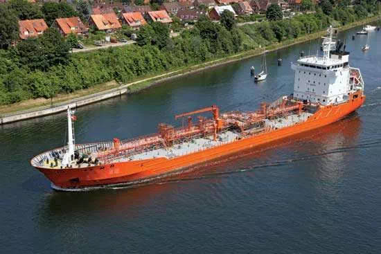
oil tankerAn oil tanker passing through the Kiel Canal in Germany.