Drilling Rig Systems
Although drilling rigs differ greatly in outward appearance and method of deployment, all rotary rigs have the same basic drilling equipment. The main component parts of a rotary rig are:
• Power system
• Hoisting system
• Circulating system
• Rotary system
• Well control system
The rig is basically comprised of a derrick, the drawworks with its drilling line, crown block and traveling block, and a drilling fluid circulation system including the standpipe, rotary hose, drilling fluid pits and pumps. These components work together to accomplish the three main functions of all rotary rigs:
• Hoisting System
• Circulating System
• Rotating System
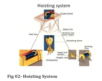
I- The Hoisting System
The derrick supports the hook and elevators by means of the traveling block, drilling line, crown block and drawworks.
The drawworks is powered by prime movers - two, three or even four engines.
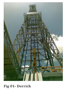
Derrick:
The derrick is a metallic structure which has four supporting legs resting on a square base. It is erected on a substructure which supports the rig floor and the rotary table and provides work space on the rig floor.
The derrick and its substructure support the weight of the drillstem at all times. The drillstem is suspended by the traveling block and drilling line, the entire load rests on the derrick. Whenever it is suspended from the crown block or resting in the rotary table. The height of the derrick does not affect its load-capacity, but it can limit the length of drill pipe sections that can be pulled out of the hole for many reasons (ex: changing drill bit). This is because the crown block must be sufficiently elevated above the rig floor.
Traveling Block, Crown Block, Drill Line and Hook:
The traveling block, crown block and drilling line are used to connect the derrick with the drill string to be lowered into or pulled out of the hole. During drilling operations, this drill string usually composed of the drill pipe, heavy weight drill pipe, drilling jar, drill collars and drill bit. The drilling line passes from the drawworks to the top of the derrick. From there, it is sheaved between the crown block and traveling block to give an eight, ten or twelve-line suspension. It is then clamped to the rig floor by the deadline anchor. The drilling line wears evenly as it is used; it has to be Cutoff time to time. The cutoff procedures are related to ton-miles of service. The ton-mile unit is calculated as the drill line moves a one-ton load a distance of one mile, and then the line receives one ton-mile of usage.
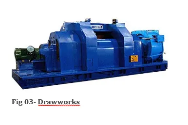
The Drawworks:
The main purpose of the drawworks is to lift the drillstring out of and to lower it back into the borehole. The drilling line is reeled on a drum in the drawworks. When engaged, the drum turns and either reel-in the drill line to raise the traveling block, or reel-out the drill line to lower it.
The drawworks is characterized by the brake system, which enables the driller to easily control a load of thousands of pounds of drillpipe or casing. There are at least two brake systems. One brake is a mechanical friction device and can bring the load to a complete stop. The other brake is hydraulic or electric; it can control the speed of the descent of a loaded traveling block, but is not capable of bringing it to a complete stop. It is used to reduce the wear on the primary friction system.
An integral part of the drawworks is the transmission system. This gives the driller a wide choice of speeds for hoisting the drillstring. The drawworks also has a drive sprocket that drives the rotary table by means of a heavy-duty chain. In some cases, however, the rotary table is driven by an independent engine or electric motor.
Another feature of the drawworks is the two catheads. The make-up cathead, on the driller’s side, is used to spin up and tighten the drillpipe joints. The other, located opposite the driller's position on the drawworks is the breakout cathead. It is used to loosen the drillpipe when the drillpipe is pulled out of hole.
An independent air hoist is used on many rigs for handling light loads around the rig-floor.
II- Circulating system:
During drilling operations, In order to circulate the drilling fluids, the circulating system, mud pumps and prime movers are used. The drilling fluids are circulated from the mud tanks, through the drillstring, down to the bit and up to the surface through annulus. The cuttings are displaced from the bottom, up to the surface and separated from the drilling fluids using the shale shakers and mud cleaner. The recovered cuttings can be used by geologists to identify which formation is being drilled.
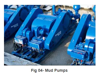
Mud pumps
The mud pump is the heart of the circulating system. In drilling rig, usually there are two mud pumps. They are used to circulate the drilling fluid from the mud pits, through the drillstring, down to the bit and return up to the surface through the annulus. There are two types of mud pumps: duplex and triplex.
The duplex pumps are double reciprocating acting. They have two cylinders, each cylinder is filled on one side of the piston with the drilling fluid, whereas in the other side the drilling fluid is being discharged. In duplex pump, the discharged volume of the drilling fluid is twice the volume of piston.
The triplex pumps are single acting pumps. They have three cylinders and the drilling fluid is filled in one side of the piston. The triplex pumps system is connected to centrifugal pumps to charge the suction parts with the drilling fluid.
The power generated by the triplex can be relatively higher then duplex because it operates at higher speed.
The mud pumps are connected to strand pipe with high pressure piping. The stand pipe is clamped to the derrick, and anchors one end of the rotary hose and keeps it clear of the rig floor during operations. The other end of the hose is connected to the swivel.
Mud Pits:
The mud pits are a series of large interconnected steel tanks fitted with agitators to keep solids in suspension. There are some pits are used for circulation and others are used for mixing and storing drilling mud. Fresh water and base oil which are used for making drilling fluids are pumped from storage tanks.
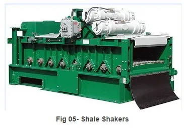
Shale Shakers:
Once the drilling fluid has completed one cycle from the mud pits and coming back to surface passing through the drill string, down to drill bit and up to the surface, it will contains solids, some gas if the drilling is performed through reservoir and other contaminants. These non-drilling fluids product or contaminants must be removed in order to keep the required properties needed to drill safely.
The drilling fluid passes over a series of vibrating screens of different mesh sizes. Tanks can also allow residues settling before the mud passed to the mud pits. Fine solids are removed by other components such as mud cleaner or centrifuges.
III-Rotating system:
Rigs can be equipped with Kelly system of top-drive system. Both systems are used to rotate the drill string and the drill bit.
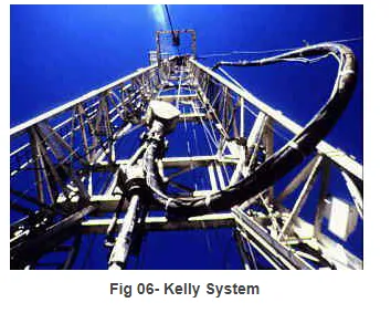
Kelly system:
The Kelly is nearly 40 feet long, hexagonal or square on the outside and hollow inside to allow the passage for the drilling fluids. The Kelly engages in the Kelly bushing, which allow the Kelly to move freely up and down even when rotating the Kelly by the rotary table. The Kelly cock valve is a safety valve which can be closed to prevent back pressure to damage surface equipment like the swivel and the rotary hose.
The hook is attached with the swivel which does not rotate but supports the Kelly. The drilling fluids are pumped into the drill string through the gooseneck connection above the swivel via the rotary hose.
The rotary motion is transmitted from the rotary table to the Kelly bushing by the master bushing. The Kelly bushing engages into the master bushing using four pins which enter in four openings. Rollers within the Kelly bushing permit the Kelly to move upwards and downward.
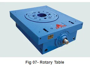
Rotary table:
The rotary table is used for two main tasks:
- Rotating the drill string
- Holding the weight of the drill string when it is not supported by the hook or the elevator.
A direct drive to the rotary is often used with independent engine or electric motor.
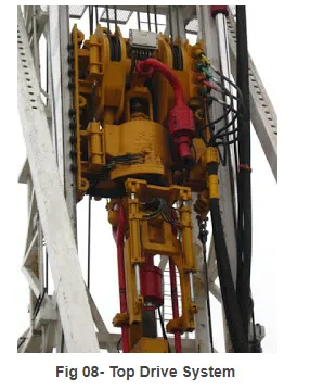
Top drive system:
It is called top drive system because the rotating motion is accomplished by a drive motor attached to the travelling block above all the drill string. An electric motor is used to generate the rotary torque which is applied to the drill string.
The main advantage of the top drive system is that connections have to be screwed or unscrewed every 30m (90 ft), because drilling can be performed by stands rather than single joint of drill pipe. The swivel and handling equipment are an integral piece of equipment in the top drive which can make the circulation and back reaming while pulling the pipe an easy task. These advantages serve to reduce drilling time which is the most important factor in drilling programming and operations.
The Kelly and the Kelly bushing are not required while using the top drive system.
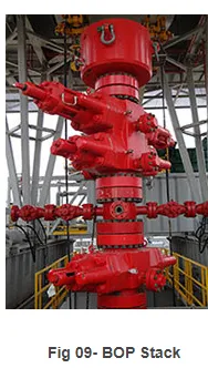
IV- BOP System:
The BOP is an important piece of equipment in the rig. It is used as second barrier against any loss of pressure control. It is fitted with:
- Annular preventer
- Rams
- Choke line
- Kill line
Annular preventer:
This part of BOP seals and closes the well by a circular piece of rubber. It can close on any pipe and casing sizes, and it closes the open hole.
Rams:
It is consisted of two rams which can move to each other. They are activated hydraulically.
Pipe ram can close on drill pipe because they have semicircular openings which allow them to seal the area around the drill pipe. Blind rams are used to close the well when pipes are not in the hole, if the blind is closed on drill pipe, this will not stop the seepage of formation fluids, because they have flat edges. Shear rams are used as last solution in well control. They can cut the pipe and close the well.
Choke line:
This line allows the circulation of the inflex to choke manifold. It has two main valves: hydraulic and manual. The manual valve is used as safety valve in case of hydraulic valve failing.
Kill line:
This line is used to inject heavy mud while well killing process. It has two valves: hydraulic and manual valves. It is fitted also with check valve or non return valve to avoid the back circulation of kill mud or formation fluids.