Distillation and Stripping
9.1 PROCESSES OF DISTILLATION AND STRIPPING
Distillation is a process in which more volatile substances in a mixture are separated from less volatile substances. This separation can be carried out either by vaporising a liquid mixture or by condensing a vapour mixture. In the actual practice of distillation, liquid containing the volatile substances is heated to generate vapour which is separated from the mixture followed by condensation of the vapours as the distillate. The residue is rich with the less volatile components. Distillation may be carried out for both batch and continuous processes. Removal of low boiling components in small amounts by heating or by steam or by gas is called stripping. This is also similar to distillation and is used to remove dissolved gases from naphtha in a stabiliser column similar to a distillation column; to remove hydrogen sulfi de from a solvent (e.g., diethyl amine) used up in a hydrogen sulfi de absorber from a hydrocarbon gas mixture; and to remove undesired light fractions from straight run fractions for adjusting the fl ash point, etc.
9.2 BATCH DISTILLATION
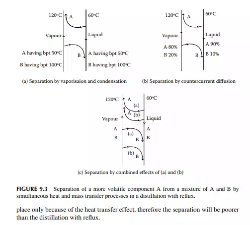
Batch distillation is carried out for testing and analysis of small-scale separation processes. In refi neries and petrochemical plants, distillation is carried out in a continuous manner for large-scale separation. As already explained in Chapter 2, crude oil and its products are analysed by ASTM and TBP distillation analysis, which are batch processes. In the ASTM distillation process, a certain amount of sample is gradually heated in a retort to separate the vapour, which is then condensed and collected as the fractions. In this process, fractions boiling with increasing boiling points (bubble points) are collected as the temperature of the retort increases. Thus, separation takes place solely by heat transfer. In a TBP distillation process, the sample is heated in the retort similarly as in the ASTM, but in a long column packed with packing materials. The vapour separated from the liquid is condensed and partly returned (refl uxed) to the retort and partly collected as the fraction. In this case, separation is enhanced by the refl ux by simultaneous heat and mass transfer of the components. As the vapour temperature rising from the retort is at a higher temperature than the temperature of the refl uxed liquid, the less volatile components are condensed from the vapour and join the refl ux stream, whereas the more volatile components in the refl ux stream are vaporised and join the vapour stream. This enhances the separation solely by heat transfer because of the temperature and phase differences. In addition to this mechanism, separation is also enhanced because of the concentration differences of the components in the vapour and liquid refl ux streams. As the vapour rising from the retort is rich with less volatile components and the refl ux is rich with more volatile components, there is a transfer of more
volatile components from the liquid to the vapour stream and less volatile components are transferred from the vapour to the liquid stream. Because of this simultaneous heat and mass transfer process, the vapour stream is enriched with more volatile components and the refl ux stream is enriched with less volatile components. Thus, fractions collected are nearly the true representative of the fractions originally present in the sample. Hence, such a distillation is called true boiling point (TBP) distillation. However, the contacting pattern of the liquid and vapour streams plays the role of separation. The more intimate the contact between the vapour and liquid streams, the greater the separation. The highest possible separation occurs with such an intimate contact when the composition of the components in the vapour and liquid reaches equilibrium. Such a state is known as vapour-liquid equilibrium (VLE). To promote the equilibrium state, contact between the liquid and vapour streams is carried out in a plate or a packed tower. A plate is a circular disk equal to the diameter of the column, with perforations or nozzles or valves through which vapour rises through the liquid hold up (liquid level) over the plate. The liquid falls from the plate through separate larger holes (known as downcomers) provided on the plate surface at suitable positions, usually at the sides of the plate. The more the number of plates, the greater will be the separation of more volatiles from the less volatiles; hence, separation is also expressed in terms of equivalent plates. In a standard TBP distillation column, packing is used that provides separation achieved by 20 equivalent plates.
9.3 BOILING POINT AND EQUILIBRIUM DIAGRAMS
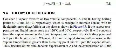
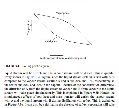
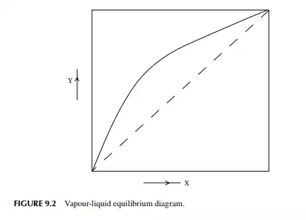
The theory of distillation is most easily understood from binary (two components) component analysis, i.e., the binary distillation process. Consider a binary mixture of two volatile components, A and B, where A is more volatile than B. If the vapour and liquid are in equilibrium, then the composition of A in the vapour and liquid phases will be functions of temperature, T, at a constant total pressure. A plot of the temperature and composition of A in the vapour and liquid phases is shown in Figure 9.1. This is called the boiling point diagram of the components, where y and x are the mole fractions of A in the vapour and liquid phases, respectively. A plot of y vs. x is known as the equilibrium diagram (Figure 9.2). Vapour composition (y) and liquid composition (x) are related by relative volatility (α) as follows
9.5 CONTINUOUS DISTILLATION
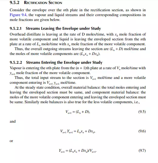
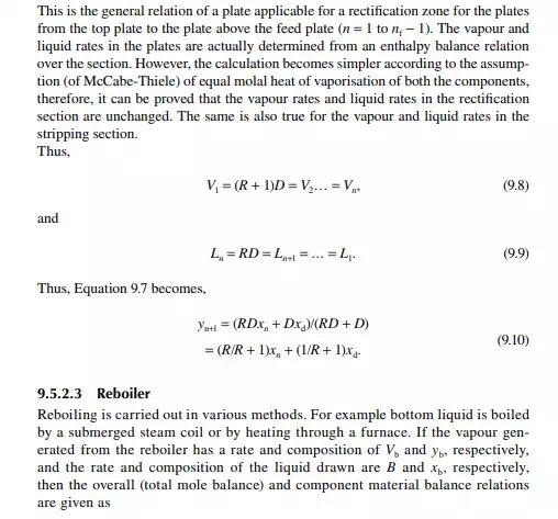
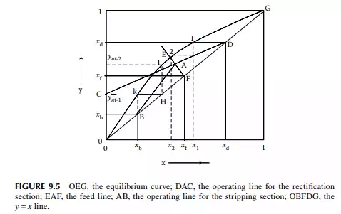
Continuous distillation is usually carried out in plated columns. Packed columns, combinations of packed sections, and plated sections are also used. Consider a plated column, as shown in Figure 9.4, which contains a number of plates (nt ), each bringing vapour and liquid streams in equilibrium such that the vapour leaving the plate and the liquid leaving the plate are in equilibrium. The column plates are provided with bubble caps for vapour rising and downcomers are provided for liquid to fl ow down. If the number of plates is counted from the top, the top plate is numbered 1 and the bottom plate is nt. The feed plate on which the feed mixture is introduced is the nf th plate. Any plate located in the column may be designated as the nth plate, plates above and below this plate are designated as n − 1th and n + 1th plates, respectively. Feed plate location divides the column into two distinct sections, namely, rectifi cation and stripping sections, which are above and below the feed plate, respectively. Vapour from the top plate is condensed by a condenser (usually water cooled) and condensate is collected in a vessel, known as the refl ux drum, from which a part of the condensate is refl uxed back to the top of the column. Condensate drawn from the refl ux drum as product is called the distillate or top product. Residue liquid from the bottom of the column enters
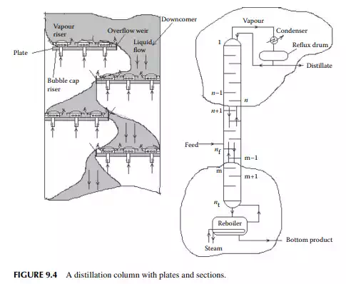
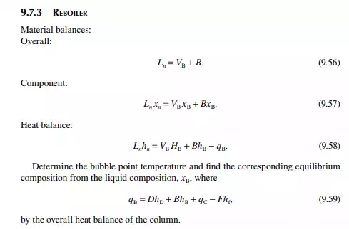
a reboiler, which partly reboils or vaporises the liquid back to the bottom plate. Liquid drawn from the reboiler is known as the bottom product or residue. The top product will be rich with a more volatile component and the bottom product will be rich with a less volatile component. Consider a feed of a binary mixture of A and B entering the feed plate of the column at a fl ow rate of F mol/time, the feed containing the more volatile component A as the zf mole fraction. The top and bottom products are withdrawn from the refl ux drum and the reboiler at the rates of D and B mol/time with the desirable compositions of A in the distillate as xd and of B in the bottom as xb mole fractions. Let us analyse the column in sections, assuming that the steady state operation is maintained such that no accumulation or depletion of any component, vapour or liquid streams occur in the plates, refl ux drum, reboiler, or any part of the column.
9.5.1 TOP REFLUX DRUM
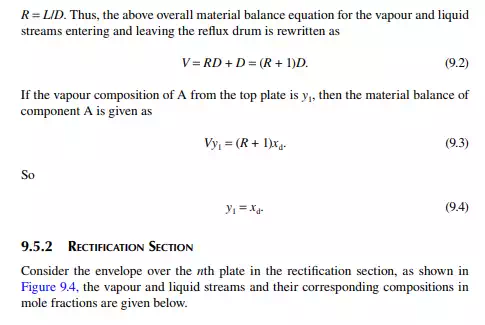
Assume that the vapour from the top plate is totally condensed to liquid, i.e., the condenser is a total condenser. If the rate of vapour leaving the top plate is V mol/ time, then V
9.7.5 TYPES OF REFLUXES
External refl uxes are the part of the vapour or liquid streams that are separated from the column, cooled (by external coolers or condensers), and returned to the column. Any refl ux returned from outside the column is external refl ux. Vapour streams leaving the top plate of the column are condensed usually by a water cooler and collected in a refl ux drum. Condensate is drawn as the top product or distillate and a part of this, known as the overhead or top refl ux, is returned back to the column top. Therefore, the overhead refl ux is an external refl ux. If the vapour is just condensed to its saturated liquid (or bubble point temperature), the overhead refl ux is then a saturated liquid refl ux. If the condensate is further cooled below the saturated liquid temperature, the refl ux is a sub-cooled refl ux. In fact, the overhead refl ux is a sub-cooled refl ux in reality. The overhead refl ux cools the uprising vapour from which the components that are at boiling point below the temperature of the overhead refl ux are condensed and separated from the vapour stream leaving the column top. The lower the temperature of the overhead refl ux, the greater this separation, causing a reduced amount of vapour fl ow to leave the column. Too low a temperature and too high an overhead refl ux fl ow rate will cause too much condensation when too little vapour will leave the column and too large a fl ow rate of liquid will fl ow down the column plates. Liquid may also weep through the risers and trickle down to the lower plates allowing no vapour to fl ow up (or pass through), causing little or no separation of the components. On the other hand, when the refl ux rate is low as compared to the vapour rising, separation will be poor due to incomplete contact of vapour with the liquid and the liquid fl ow rate is affected by the vapour fl ow rate, i.e., loading is initiated and when the vapour fl ow rises further resisting liquid to fl ow down. Foaming may also be generated over the plate surrounding the risers. This situation is called fl ooding, which, in fact, is the phenomenon limiting the maximum vapour velocity in the column. Hence, the maximum fl ow rates of both the liquid and vapour in a distillation column must be
taken care of as far as the quality of the products is concerned. A circulating refl ux or pumparound are other types of external refl ux where the liquid stream separated from the column is cooled in an external cooler either by a water cooler or by other cold streams and returned back to the column. External refl uxes keep the heat load in the column under control.
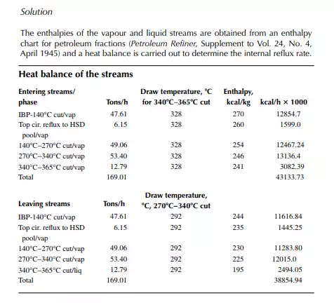
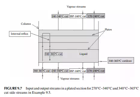
9.7.6 INTERNAL REFLUX
A part of the volatile components in the vapour stream gets condensed as it rises up the column as the temperature in the upper plates is lower. This condensate then falls to the lower plate, only to be vaporised again and condensed in the upper plates. This process is continuously repeated and the stream, which takes part in the repeated condensation and vaporisation without leaving the column, is known as the internal refl ux. The internal refl ux fl ow cannot be physically measured, but it can be evaluated by making an enthalpy balance calculation over the plates.
9.7.7 MINIMUM REFLUX
If the refl ux increases, the distillates become more enriched with more volatile components for a column of a specifi ed number of plates. The higher the refl ux, the more the pumping cost, the less the distillate rate, the more heater duty, etc., causing the cost of the operation to increase directly with the increase in the refl ux rate. On the other hand, if the refl ux is reduced, the number of plates in the column required to maintain the same degree of enrichment of more volatile components in the top product (or enrichment of less volatile components in the bottom product) will have to be increased, leading to high cost of equipment. In order to reduce the cost of the operation, the refl ux rate is minimized so that total cost which is the sum of the cost of operation and the fi xed cost becomes minimum. This refl ux is called the optimum refl ux rate. Thus, the actual operating refl ux rate is maintained near the optimum rate.
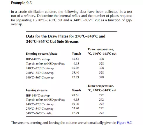
9.8 GAP AND OVERLAP
In petroleum distillation, the separated products from the distillation column are, in fact, a mixture of hydrocarbons, and the use of VLE constants (k) are not exact, though their average values are available for certain light fractions. Empirical methods are widely used in the absence of VLE information for boiling fractions. The degree of separation and the quality of the products are conveniently expressed in terms of gap or overlap of the separated streams. Gap is defi ned as the difference between the 5% and the 95% points of the heavier and the lighter fractions, respectively. For instance, if a 5% point of kerosene is 145°C and a 95% point of naphtha is 140°C, then the gap between them is + 5°C. This indicates that the naphtha is completely free from the kerosene hydrocarbons and the kerosene is also free from the naphtha hydrocarbons, i.e., the ASTM distillation curves for these products are not intersecting anywhere, hence no mix-up. On the other hand, if the 5% and 95% points were 140°C and 145°C, respectively, for kerosene
and naphtha, then there would be an overlap, i.e., gap = −5°C or overlap = 5°C. In this case of overlap, some of the naphtha components (heavier parts) will be present in the kerosene and some of the kerosene components (lighter parts) will be found in the naphtha. Thus, this 5% and 95%-point difference is positive for the gap and negative for the overlap. Gap or overlap are monitored to adjust the initial boiling point (IBP) or fl ash point of the adjacent streams from a column. A higher refl ux rate and a larger number of plates maintain a good degree of separation or gap, but at high cost of refi ning. Designers, therefore, prefer to compromise on overlap and gap. In fact, internal refl ux between the side stream drawing sections can be varied to a certain extent in a specifi ed column and hence gap/overlap can be manipulated. The presence of steam also enhances gap/overlap between the side products.
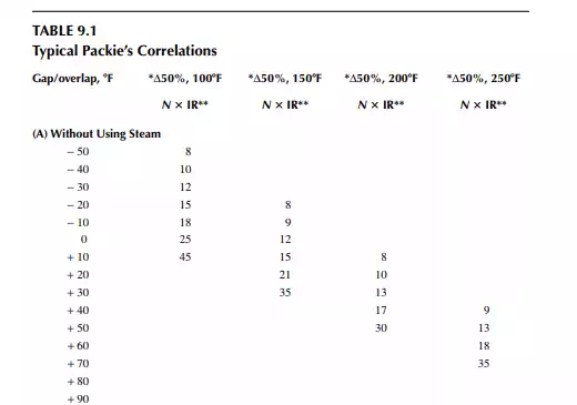
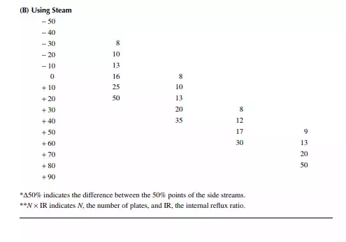
9.9 PACKIE’S CORRELATION
Packie has developed correlations between the number of plates and the internal refl ux ratio between the side streams as a function of gap/overlap. Some of this information is presented in Table 9.1.