Time-delayed RC, TL-RC
For TL-RC, a discrete reservoir with a circular connection topology is formed due to the circular symmetry of a single delay line . It uses only a single nonlinear node with delayed feedback. Figure 4 shows the general structure of a delay line based reservoir computer. In essence, TL-RC constitutes an exchange between space and time. In the input layer, a temporal input-mask Win is used to map the input information u(n) to the TL-RC’s temporal dimensions, which results in N-dimensional vector uin=(uin1,uin2,⋯,uinN)uin=(u1in,u2in,⋯,uNin) at each n, where n ∈ {1, 2, …, T}. Thus, the TL-RC has to run at an N times higher speed compared with an N-node SD-RC, which is demanding for the modulators and bandwidth of the detector. Time multiplexing now assigns each uin(n) to a temporal position denoted by l × δτ, where l ∈ {1, 2, ⋯, N} denotes the index of the virtual nodes, δτ denotes the temporal separation or distance of virtual nodes. The mask duration τm equals l × δτ, while τD denotes the duration of the delay in the feedback loop. In this way, the input is mapped to the reservoir layer. Each virtual node can be regarded as a measuring point or tap in the delay line, whose value can be detected by a single detector. In the training phase, the reservoir state is sampled per δτ. The samples are then reorganized in a state matrix which is used to calculate the readout matrix. Two mechanisms have been proposed to realize the internal connectivity inside the reservoir. The first uses the system’s impulse response function h(t), while the other use the de-synchronization between the input mask duration τm and the delay duration τD.
Fig. 4
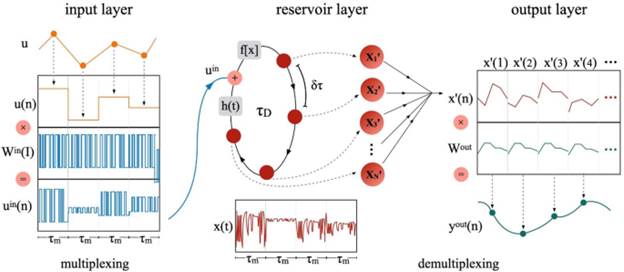
Schematic illustration of the time-delay reservoir computer . The input layer is implemented by modulating input u(n) with temporal mask to create input uin(t). τm denotes mask duration, τD denotes the duration of the delay in the feedback loop, δτ denotes the temporal separation or distance of virtual nodes. The reservoir state is detected during one delay .
The first photonic implementations of RC based on time delay were independently by Larger et al. and Paquot et al.. Both implementations are based on the optoelectronic implementation of an Ikeda-like ring optical cavity. These systems use the concept of dynamical coupling via impulse response function h(t). For this, the temporal duration of a single node δτ is shorter than the system’s response time, which results in connections according to the convolution-response h(t) and the neighboring nodes owing to inertia-based coupling. This approach is conductive to maximize the speed of TL-RC.
The other pioneering work was demonstrated by Duport et al. . In this setup, the δτ is significantly larger than the system’s response time, while input mask duration τm is smaller than the delay duration τD. A local coupling is introduced by setting δτ = τD/(N + k), which results in node xl(n) is delay coupled to the node xl − k(n − 1). This approach makes the mathematical model and numerical simulation process simplified. The operational bandwidth is reduced compared with the first approach, which may be profitable for the system’s signal to noise ratio.
Following the above mentioned pioneering works, the TL-RC based on optoelectronic oscillators has been tested on various tasks that can be divided into two main categories: classification and prediction. More details can be found in the Yanne’s review . Except for the optoelectronic implementation, another branch of TL-RC is all-optical RC. In this branch, the nonlinear node is implemented by optical components such as semiconductor optical amplifier , semiconductor saturable absorber mirror , external-cavity semiconductor laser , and vertical cavity surface-emitting lasers .
The main advantages of optical/optoelectronic implementation of RC are the low power consumption and high processing speed, which results from the parallelism and speed of light. Integration or miniaturization of the system are the main challenges that optoelectronic/ optical RC need to be solved before commercial applications. More importantly, the killer application of optoelectronic/optical RC are urgently to be demonstrated.