In deadlock avoidance, the request for any resource will be granted if the resulting state of the system doesn't cause deadlock in the system. The state of the system will continuously be checked for safe and unsafe states.
In order to avoid deadlocks, the process must tell OS, the maximum number of resources a process can request to complete its execution.
The simplest and most useful approach states that the process should declare the maximum number of resources of each type it may ever need. The Deadlock avoidance algorithm examines the resource allocations so that there can never be a circular wait condition.
Safe and Unsafe States
The resource allocation state of a system can be defined by the instances of available and allocated resources, and the maximum instance of the resources demanded by the processes.
A state of a system recorded at some random time is shown below.
Process | Type 1 | Type 2 | Type 3 | Type 4 |
A | 3 | 0 | 2 | 2 |
B | 0 | 0 | 1 | 1 |
C | 1 | 1 | 1 | 0 |
D | 2 | 1 | 4 | 0 |
Process | Type 1 | Type 2 | Type 3 | Type 4 |
A | 1 | 1 | 0 | 0 |
B | 0 | 1 | 1 | 2 |
C | 1 | 2 | 1 | 0 |
D | 2 | 1 | 1 | 2 |
E = (7 6 8 4)
P = (6 2 8 3)
A = (1 4 0 1)
Above tables and vector E, P and A describes the resource allocation state of a system. There are 4 processes and 4 types of the resources in a system. Table 1 shows the instances of each resource assigned to each process.
Table 2 shows the instances of the resources, each process still needs. Vector E is the representation of total instances of each resource in the system.
Vector P represents the instances of resources that have been assigned to processes. Vector A represents the number of resources that are not in use.
A state of the system is called safe if the system can allocate all the resources requested by all the processes without entering into deadlock.
If the system cannot fulfill the request of all processes then the state of the system is called unsafe.
The key of Deadlock avoidance approach is when the request is made for resources then the request must only be approved in the case if the resulting state is also a safe state.
The resource allocation graph is the pictorial representation of the state of a system. As its name suggests, the resource allocation graph is the complete information about all the processes which are holding some resources or waiting for some resources.
It also contains the information about all the instances of all the resources whether they are available or being used by the processes.
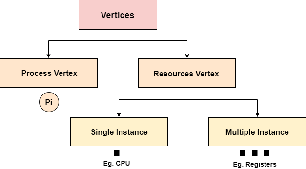
In Resource allocation graph, the process is represented by a Circle while the Resource is represented by a rectangle. Let's see the types of vertices and edges in detail.
Vertices are mainly of two types, Resource and process. Each of them will be represented by a different shape. Circle represents process while rectangle represents resource.
A resource can have more than one instance. Each instance will be represented by a dot inside the rectangle.
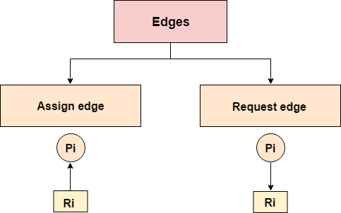
Edges in RAG are also of two types, one represents assignment and other represents the wait of a process for a resource. The above image shows each of them.
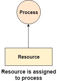
A resource is shown as assigned to a process if the tail of the arrow is attached to an instance to the resource and the head is attached to a process.
A process is shown as waiting for a resource if the tail of an arrow is attached to the process while the head is pointing towards the resource.

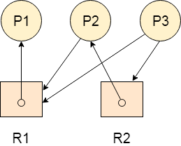
Let'sconsider 3 processes P1, P2 and P3, and two types of resources R1 and R2. The resources are having 1 instance each.
According to the graph, R1 is being used by P1, P2 is holding R2 and waiting for R1, P3 is waiting for R1 as well as R2.
The graph is deadlock free since no cycle is being formed in the graph.
If a cycle is being formed in a Resource allocation graph where all the resources have the single instance then the system is deadlocked.
In Case of Resource allocation graph with multi-instanced resource types, Cycle is a necessary condition of deadlock but not the sufficient condition.
The following example contains three processes P1, P2, P3 and three resources R2, R2, R3. All the resources are having single instances each.
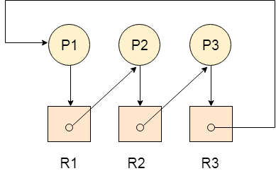
If we analyze the graph then we can find out that there is a cycle formed in the graph since the system is satisfying all the four conditions of deadlock.
Allocation matrix can be formed by using the Resource allocation graph of a system. In Allocation matrix, an entry will be made for each of the resource assigned. For Example, in the following matrix, en entry is being made in front of P1 and below R3 since R3 is assigned to P1.
Process | R1 | R2 | R3 |
P1 | 0 | 0 | 1 |
P2 | 1 | 0 | 0 |
P3 | 0 | 1 | 0 |
In request matrix, an entry will be made for each of the resource requested. As in the following example, P1 needs R1 therefore an entry is being made in front of P1 and below R1.
Process | R1 | R2 | R3 |
P1 | 1 | 0 | 0 |
P2 | 0 | 1 | 0 |
P3 | 0 | 0 | 1 |
Neither we are having any resource available in the system nor a process going to release. Each of the process needs at least single resource to complete therefore they will continuously be holding each one of them.
We cannot fulfill the demand of at least one process using the available resources therefore the system is deadlocked as determined earlier when we detected a cycle in the graph.