Ethernet Switches
Switches join separate physical Ethernets (or sometimes Ethernets and other kinds of networks). A switch has two or more Ethernet interfaces; when a packet is received on one interface it is retransmitted on one or more other interfaces. Only valid packets are forwarded; collisions are not propagated. The term collision domain is sometimes used to describe the region of an Ethernet in between switches; a given collision propagates only within its collision domain.
Switches have revolutionized Ethernet layout: all the collision-detection rules, including the rules for maximum network diameter, apply only to collision domains, and not to the larger “virtual Ethernets” created by stringing collision domains together with switches. As we shall see below, a switched Ethernet also offers much more resistance to eavesdropping than a non-switched (eg hub-based) Ethernet.
Switch Costs In the 1980’s the author once installed a two-port 10-Mbps Ethernet switch (then called a “bridge”) that cost $3000; cf the [MB76] quote at 2 Ethernet. Today a wide variety of multiport 100-Mbps Ethernet switches are available for around $10, and almost all installed Ethernets are fully switched.
Like simpler unswitched Ethernets, the topology for a switched Ethernet is in principle required to be loop free. In practice, however, most switches support the spanning-tree loop-detection protocol and algorithm, 2.5 Spanning Tree Algorithm and Redundancy, which automatically “prunes” the network topology to make it loop-free while allowing the pruned links to be placed back in service if a primary link fails.
While a switch does not propagate collisions, it must maintain a queue for each outbound interface in case it needs to forward a packet at a moment when the interface is busy; on (rare) occasion packets are lost when this queue overflows.
Ethernet Learning Algorithm
Traditional Ethernet switches use datagram forwarding as described in 1.4 Datagram Forwarding; the trick is to build their forwarding tables without any cooperation from ordinary, non-switch hosts. Indeed, to the extent that a switch is to act as a drop-in replacement for a hub, it cannot count on cooperation from other switches.
The solution is for the switch to start out with an empty forwarding table, and then incrementally build the table through a learning process. If a switch does not have an entry for a particular destination, it will fall back to flooding: it will forward the packet out every interface other than the one on which the packet arrived. This is sometimes also called “unknown unicast flooding”; it is equivalent to treating the destination as a broadcast address. The availability of fall back-to-flooding for unknown destinations is what makes it possible for Ethernet switches to learn their forwarding tables without any switch-to-switch or switch-to-host communication or coordination.
A switch learns address locations as follows: for each interface, the switch maintains a table of physical (MAC) addresses that have appeared as source addresses in packets arriving via that interface. The switch thus knows that to reach these addresses, if one of them later shows up as a destination address, the packet needs to be sent only via that interface. Specifically, when a packet arrives on interface I with source address S and destination unicast address D, the switch enters xS,Iy into its forwarding table.
To actually deliver the packet, the switch also looks up the destination D in the forwarding table. If there is an entry xD,Jy with J‰I – that is, D is known to be reached via interface J – then the switch forwards the packet out interface J. If J=I, that is, the packet has arrived on the same interfaces by which the destination is reached, then the packet does not get forwarded at all; it presumably arrived at interface I only because that interface was connected to a shared Ethernet segment that also either contained D or contained another switch that would bring the packet closer to D. If there is no entry for D, the switch must flood the packet out all interfaces J with J‰I; this represents the unknown-destination fallback to flooding. After a short while, the fallback-to-flooding alternative is needed less and less often, as switches learn where the active hosts are located. (However, in some switch implementations, forwarding tables also include timestamps, and entries are removed if they have not been used for, say, five minutes.)
If the destination address D is the broadcast address, or, for many switches, a multicast address, broadcast (flooding) is required. Some switches try to keep track of multicast groups, so as to forward multicast traffic only out interfaces with known subscribers;
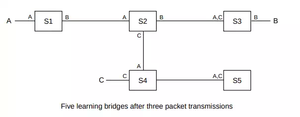
In the diagram above, each switch’s tables are indicated by listing near each interface the destinations (identified by MAC addresses) known to be reachable by that interface. The entries shown are the result of the following packets:
· A sends to B; all switches learn where A is
· B sends to A; this packet goes directly to A; only S3, S2 and S1 learn where B is
· C sends to B; S4 does not know where B is so this packet goes to S5; S2 does know where B is so the packet does not go to S1.
It is worth observing that, at the application layer, hosts do not commonly identify one another by their MAC addresses. In an IPv4-based network, the use of ARP (7.9 Address Resolution Protocol: ARP) to translate from IPv4 to MAC addresses would introduce additional broadcasts, which would cause the above scenario to play out differently.
Switches do not automatically discover directly connected neighbors; S1 does not learn about A until A transmits a packet.
Once all the switches have learned where all (or most of) the hosts are, each packet is forwarded rather than flooded. At this point packets are never sent on links unnecessarily; a packet from A to B only travels those links that lie along the (unique) path from A to B. (Paths must be unique because switched Ethernet networks cannot have loops, at least not active ones. If a loop existed, then a packet sent to an unknown destination would be forwarded around the loop endlessly.)
Switches have an additional privacy advantage in that traffic that does not flow where it does not need to flow is much harder to eavesdrop on. On an unswitched Ethernet, one host configured to receive all packets can eavesdrop on all traffic. Early Ethernets were notorious for allowing one unscrupulous station to capture, for instance, all passwords in use on the network. On a fully switched Ethernet, a host physically sees only the traffic actually addressed to it; other traffic remains inaccessible. This switch-based eavesdropping protection is, however, potentially vulnerable to attackers flooding the network with fake source addresses, forcing switches into fallback-to-flooding mode.
CAM Table On Cisco switches, the forwarding table is often called the CAM table, after the specialized high-speed content-addressable memory used to store it.
Typical large switches have room for a forwarding table with 104 - 105 entries, though fully switched networks at the upper end of this size range are not common. The main size limitations specific to switching are the requirement that the topology must be loop-free (thus disallowing duplicate paths which might otherwise provide redundancy), and that all broadcast traffic must always be forwarded everywhere. As a switched Ethernet grows, broadcast traffic comprises a larger and larger percentage of the total traffic, and the organization must at some point move to a routing architecture. A common recommendation is to have no more than 1000 hosts per LAN (or VLAN, 2
One of the differences between an inexpensive Ethernet switch and a pricier one is the degree of internal parallelism it can support. If three packets arrive simultaneously on ports 1, 2 and 3, and are destined for respective ports 4, 5 and 6, can the switch actually transmit the packets simultaneously? A simple switch likely has a single CPU and a single memory bus, both of which can introduce transmission bottlenecks. For commodity five-port switches, at most two simultaneous transmissions can occur; such switches can generally handle that degree of parallelism. It becomes harder as the number of ports increases, but at some point the need to support full parallel operation can be questioned; in many settings the majority of traffic involves one or two server or router ports. If a high degree of parallelism is in fact required, there are various architectures – known as switch fabrics – that can be used; these typically involve multiple simple processor elements.