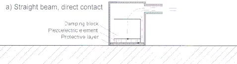
Fig. 1a: Basic construction of ultrasonic probes.
Piezoelectric materials for ultrasonic probes
Probes form the actual core in all non-destructive ultrasonic inspection procedures: The fact whether a workpiece can be inspected or not depends upon them. In numerous cases, especially if a workpiece has a complicated geometry or the inspection has to be done under unusual conditions, ultrasonic inspection becomes only feasible by use of probes, which have appropriate acoustic properties. In any case is the choice of the correct probe is decisive for the quality and the reliability of inspection results.
Today, ultrasonic probes work almost exclusively according to the piezoelectric effect. Fig. 1 shows the basic construction of four fundamental probe types. In the vertical or straight beam probe (Fig. 1a), the piezoelectric element, which converts electrical energy into mechanical energy and vice versa, is mechanically attached to a backing material, most often called the damping block. The acoustic impedance of the damping block must be close to that of the piezoelectric material in order to suppress ringing resp. to enlarge the bandwidth. The second task of the damping block is to absorb that part of ultrasonic energy, generated by the piezoelectric element, which is going backward. A protective and/or matching layer in front ensures that as much of the acoustic energy as possible is transmitted into the workpiece. It also protects the probe against mechanical damage, while it is moved over a workpiece, which may have a rough surface, or against chemical damage, when chemically agressive fluids are used as couplants.
Fig. 1a: Basic construction of ultrasonic probes.
With the angle beam probe (Fig. 1b), the ultrasound is transfered into the workpiece under at a specified angle. The TR probe (Fig. 1c) consists of one separate transmitter and receiver element each. Their sound field characteristics overlap in the workpiece. The piezo-elements are mounted on plastic wedges, which are generally made of plexiglass, polystyrene or other plastic materials of low acoustic absorption. Usually an acoustic matching layer is placed between the piezoelectric element and the plastic wedge. This ensures good energy transmission from the piezo element into the wedge. It also acts as a medium mechanical damping of the piezoelectric element. These facts lead to a high sensitivity, rather short pulses and a high bandwidth. Therefore, angle beam probes build up like this do not need a separate backing material (damping block) on the rear face of the piezoelectric element, as far as not the extremely short pulses of thickness probes are expected from the probe.
The construction of the "Delay line" probe (Fig. 1d) complies basically with that of the vertical beam probe. However here, the sound is transmitted into the workpiece via an additional delay-line made of plastics with low ultrasonic absorption. The delay line can be either rigidly fixed to the front face of the vertical probe or can be interchangeable. The time delay until the ultrasonic signal enters the workpiece avoids, that echoes from flaws close to the surface appear within the dead zones of the ultrasonic flaw detector, which are caused by the high voltage excitation pulses. Use of delay-line probes is a simple measure to have an excellent near field resolution.
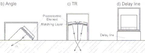
Fig. 1b,c,d: Basic construction of ultrasonic probes.
Depending on the application, probes also differ with respect to the size of the active piezoelectric elements, their frequency, bandwidth and the basic design. Fig. 2 shows a few typical models. The ones on the left are for manual testing, the ones on the right are water-proof probes, used for immersion technique, while the probes in the middle are angle beam probes.
The sound field characteristics of a probe, which are expected under normal inspection conditions, are generally derived from the diameter and the frequency of the piezoelectric element. Most often the user knows exactly these properties of "his" probe, but he isn´t quite familiar with the details regarding the physical and acoustic properties of the used piezoelectric material. However, this knowledge can not only contribute to a better technical understanding of the basic way in which the probe works, but also gives an insight into the behaviour of the probe under various conditions. This knowledge can be also helpful when trying to choose the correct or under given circumstances best working type of probe.
The following article is therefore intended to introduce the different types of piezoelectric materials currently in use. We aim to explain their strengths and weaknesses and to show, how they can be exploited for various probe designs. Additional application examples are given.
The materials from the early days of ultrasonic technology such as quartz, lithium sulphate or barium titanate are almost never used today. Instead, new powerful piezoelectric materials are available, but their basic acoustic and electric characteristics are very different. Depending on the application, the one or other material is more advantageous due to physical or economic reasons, or simply because of a less complicated manufacturing process.
Table 1 shows the important physical characteristics of piezoelectric materials used today to generate ultrasound. Lead zirconate titanate (PZT) is most probably the best known material. Along with lead titanate (PT) and lead metaniobate (PbNb2O6), it is one of today's ceramic piezoelectric materials.
Table 1 Characteristics of Piezoelectric Materials | |||||
Physical Property | Lead Zirkonate Titanate PZT-5 | Lead Titanate PT | Lead Metaniobate PbNb2O6 | Polyviylidenefluoride PVDF (Copolymere) | 1-3 Composite |
Acoustic Impedance Z [10 exp 6 kg/m²s] | 33,7 | 33 | 20,5 | 3,9 | 9 |
Resonant Frequency f [MHz] | < 25 | < 20 | < 30 | 160 -10 (55 - 2) | < 10 |
Coupling Coefficient (thickness mode) kt | 0,45 | 0,51 | 0,30 | 0,2 (0,3) | 0,6 |
Coupling Coefficient (radial mode) kp | 0,58 | < 0,01 | < 0,1 | 0,12 (k31) | ~ 0,1 |
Relative Dielectricity er | 1700 | 215 | 300 | 10 | 450 |
Maximum Temperature [°C] | 365 | 350 | 570 | 80 | 100 |
The acoustic impedances of all the piezoceramic materials are basically high and comparable to many metallic or ceramic solids, but they differ. This is as well of technical importance as the differences in their relative dielectricities (r and their coupling coefficients kp for radial vibrations. The coupling coefficient for radial vibrations indicates to what extent a piezo-element converts energy into radial modes, which are perpendicular to the thickness mode. Radial modes should be suppressed, since they cause undesired signal distortions. They are located at low frequencies, because they correspond to the lateral dimensions of the piezoelectric element. Lead titanate is the only piezoelectric material with a neglegibly small kp coefficient.
Piezoceramics are used for up to a maximum of 30 MHz. The electromechanical coupling coefficient kt is a measure of the fracture of electrical energy, which is converted into mechanical energy in the thickness mode, in other words, a type of level for the efficiency of generating ultrasound in that vibrational mode, which is utilized in probes. The coupling coefficient of piezo ceramics is basically high. However, if ultrasound shall be radiated into liquids or plastics, most part of the acoustic energy generated by the piezoceramic element is reflected at the boundary between the piezoelectric material and the medium of propagation. Due to the low acoustic impedance of liquids and plastics (from 1.5 to 3x10⁶ kg/m² sec) and the high impedance of ceramics the reflection coefficient at that boundary is far more than 90%. Therefore, only a fraction of the acoustic energy generated by the piezoelectric element is transferred into the medium of propagation or into the workpiece. Piezoelectric plastics like PVDF or related copolymers are better matched to the low acoustic impedance of liquids or plastics. In addition, they are mechanically flexible. With very thin foils it is even possible to generate ultrasound at frequencies up to 160 MHz. Unfortunately PVDF is less sensitive than ceramics, as can be recognized from the coupling coefficient kt for the thickness mode. Piezoelectric PVDF-foils should only be used to a maximum of 80°C, since depolarisation sets in and they loose their piezoelectricity at higher temperatures.
The so-called 1-3 composite materials [1,2] appear more promising. They have an extraordinarily high coupling coefficient kt , while the couplig coefficient of the transverse (radial) mode is quite low. In addition, they form an in-between stage between piezoelectric ceramics and polymers. Fig. 3 shows the schematic structure of 1-3 composite materials: They consists of ceramic rods, which are arranged in parallel to one another, embedded in a epoxy resin matrix. The rods are generally made of high-density PZT.