Measuring Magnetic Fields
When performing a magnetic particle inspection, it is very important to be able to determine the direction and intensity of the magnetic field. As discussed previously, the direction of the magnetic field should be between 45 and 90 degrees to the longest dimension of the flaw for best detectability. The field intensity must be high enough to cause an indication to form, but not too high to cause nonrelevant indications to mask relevant indications. To cause an indication to form, the field strength in the object must produce a flux leakage field that is strong enough to hold the magnetic particles in place over a discontinuity. Flux measurement devices can provide important information about the field strength.
Since it is impractical to measure the actual field strength within the material, all the devices measure the magnetic field that is outside of the material. There are a number of different devices that can be used to detect and measure an external magnetic field. The two devices commonly used in magnetic particle inspection are the field indicator and the Hall-effect meter, which is also called a gauss meter. Pie gauges and shims are devices that are often used to provide an indication of the field direction and strength but do not actually yield a quantitative measure. They will be discussed in a later section.
Field Indicators
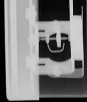
Field indicators are small mechanical devices that utilize a soft iron vane that is deflected by a magnetic field. The X-ray image below shows the inside working of a field meter looking in from the side. The vane is attached to a needle that rotates and moves the pointer for the scale. Field indicators can be adjusted and calibrated so that quantitative information can be obtained. However, the measurement range of field indicators is usually small due to the mechanics of the device. The one shown to the right has a range from plus 20 gauss to minus 20 gauss. This limited range makes them best suited for measuring the residual magnetic field after demagnetization.
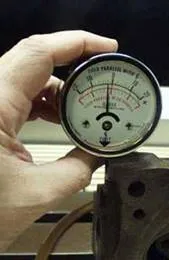
A field indicator is shown checking for residual magnetism in this movie. (194 MB mov)
Hall-Effect (Gauss/Tesla) Meter
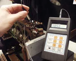
A Hall-effect meter is an electronic device that provides a digital readout of the magnetic field strength in gauss or tesla units. The meters use a very small conductor or semiconductor element at the tip of the probe. Electric current is passed through the conductor. In a magnetic field, a force is exerted on the moving electrons which tends to push them to one side of the conductor. A buildup of charge at the sides of the conductors will balance this magnetic influence, producing a measurable voltage between the two sides of the conductor. The presence of this measurable transverse voltage is called the Hall-effect after Edwin H. Hall, who discovered it in 1879.
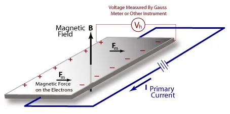
The voltage generated Vh can be related to the external magnetic field by the following equation.
Vh = I B Rh / b
Where:
Vh is the voltage generated.
I is the applied direct current.
B is the component of the magnetic field that is at a right angle to the direct current in the Hall element.
Rh is the Hall Coefficient of the Hall element.
b is the thickness of the Hall element.
Probes are available with either tangential (transverse) or axial sensing elements. Probes can be purchased in a wide variety of sizes and configurations and with different measurement ranges. The probe is placed in the magnetic field such that the magnetic lines of force intersect the major dimensions of the sensing element at a right angle. Placement and orientation of the probe is very important and will be discussed in a later section.
|