Automated Contour Following for NDT Ultrasonic Testing of Large Aerospace Parts
The introduction of automated ultrasonic testing has benefited the
nondestructive testing (NDT) field in terms of increased inspection speed,
imaging capabilities and repeatability. Ultrasonic immersion tanks and squirter
systems are well suited for flaw detection of large aerospace parts.
Complex shaped aerospace parts that present inclined, curved or multiple
surfaces require more advanced scanning schemes in order to be inspected
properly. Contour surface following capabilities represents an interesting
scanning option to inspect the whole part as a single surface since it provides
a controlled and repeatable way of performing the required inspection. However,
its realization is very challenging as it requires multi-axis robotic
manipulators with advanced tridimensional scanning capabilities. In addition,
such manipulator solution must provide accurate transducer positioning with
high-precision and repeatability.
Contour Following
In the context of ultrasonic inspection, contour following can be described as a scanner’s ability to do a controlled displacement of one or multiple axes, with the objective to move around a curved, round or inclined surface with constant transducer orientation and distance (water path). When performing an ultrasonic inspection with large immersion or squirter system, the orientation of the transducer must be controlled with a high degree of precision in order to follow the part contour adequately. Of course, this must be accomplished without any collisions between the scanning head and the inspected part.
Defining the Contour Following Path
Before an inspection is performed with contour following, the displacement path of the scanner’s axes must be properly defined in order to obtain constant water column and transducer angle. We also need to accurately know the inspected surface position. To define the part or part surface we can either use a computer-aided design (CAD) file or by teaching the part surface point-by-point. The part teaching approach, is often referred to as a Teach and Learn. In both cases, coordinates and orientation (normal vectors) of points on the part surface must sufficiently be sampled.

Setup of TecView™ 3D for contour following
After a proper sampling of the desired area has been done, interpolation is performed to predict the position of the part surface between the recorded coordinates and to calculate a valid path trajectory for the scanner’s axes.
Validation of the Contour Following Path
An important step in the definition of the part contour is the validation of the scanner’s displacement path in the interpolated areas, which can be done by comparing the deviation of the water path and incidence angle with regards to an acceptable error. While moving around the contour, a visual alarm can be set to advise the operator of deviations beyond this acceptable error. While water path deviations can be monitored from the time-of-flight of surface echoes, validating the incidence angle requires an indirect measurement. Setting a tolerance on the amplitude variations of the surface echo recorded at 0-degree incidence represents an efficient way of monitoring errors in the surface contour orientation; a large variation in the amplitude of the surface echo may indicate that the incidence angle at that location is not 0 degrees. If either alarm is triggered, a verification of the incidence angle can be done at the problematic locations and surface coordinates can be added or modified to increase the part definition accuracy.
Calculation of Axes Trajectories
After the part contour has been defined and validated, contour following algorithms can be used to calculate the axes trajectories covering the complete part contour without any risk of collisions. TecView 3D maps the selected part surfaces to the appropriate scanner axes and creates a 2D parametric space that defines the surface. The 2D surface can be defined in multiple ways from the defined surface contour (extrusion, angular revolution, rotational symmetry).
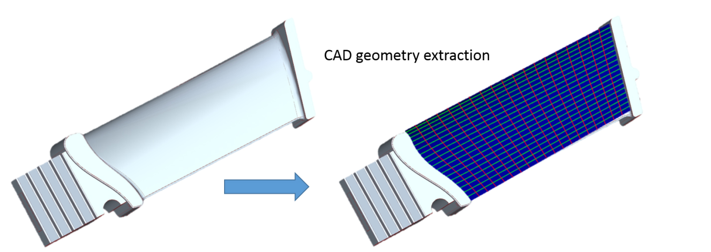
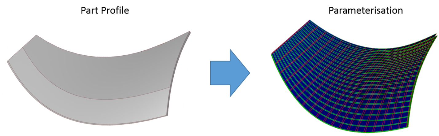
Examples of CAD geometry extraction and parameterization in TecView™ 3D
Starting with good scanner metrological alignment conditions, reliable 3D contour following performances are then obtained with excellent transducer positional accuracy and repeatability.
Part Positioning for Contour Following Inspection
Part positioning is achieved the same way a contour definition is done, i.e. by recording a set of points that defines the surface. Part surface is located according to the water path measured by an interface gate placed over the Front wall echo. Points are acquired at different location on the surface to construct a point cloud, and an automatic repositioning tool is used to fit the pre-defined surface to the point cloud. Manual positioning tools are also located within the surface reposition control box.

TecView 3D automatic positioning tool
Contour Following Inspection Results
The example presented below demonstrates how a 3D contour following scanning solution and automated UT testing are being used to perform inspections of fan blades and fan cases. The first figure shows an example of a C-scan image obtained on a sample composite fan blade containing disbonds. These were created with Teflon inserts between the layers of the composite blade. The C-scan result represents a color-coded 3D presentation of the data collected during an automated inspection of the blade. The red spots on the C-scans represent the detected disbonds defects. Similarly, the adjacent figure displays a C-scan with defects obtained from a tested engine fan case sample.

C-Scan image of sample engine fan blade

C-Scan image of sample engine fan case