Inspection of Composite Materials in Aerospace Applications
The use of composite materials is widespread and still growing especially in the aerospace industry. Currently, aircraft designers are using significant amounts of composite materials for the design of airframe and engine components. Such a design solution provides significant weight reduction, reduced fuel consumption and improved engine durability. Another advantage is that composite materials can be formed into more complex shapes than their metallic counterparts, making them hard to inspect for manufacturing anomalies or defects.
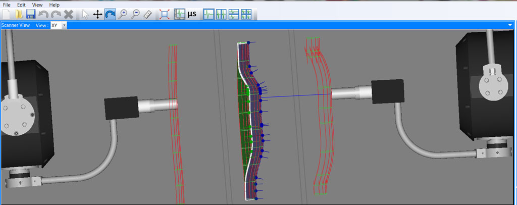
TecView CAD import of composite sample
The use of NDT for composites
The safety nature of aircraft critical components and their reliability requirements entail rigorous non-destructive testing for the evaluation and detection of any defects. Non-destructive ultrasonic testing (UT) is the most widely used technique for testing composite materials for both manufacturing and in-service defects such as porosities, disbonds, voids and delaminations. UT testing of composite materials have several advantages: it can detect and characterize small defects by testing in through-transmission or pulse-echo modes, the UT results can be presented in color coded C-Scans and can be produced by combining the ultrasonic instrument and the probe along with an automated Cartesian robots or squirters gantry systems.
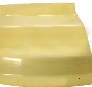
Panel of composite materials
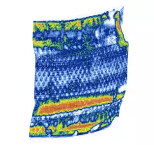
C-Scan inspection results
NDT Inspection Challenges
The biggest challenge is to perform NDT inspections of complex composite parts and structures which have complicated curvatures, surfaces and free form shapes that do not have any axis of symmetry while having varying thicknesses.

Aircraft engine composite fan blade
Solution
To overcome the above mentioned challenges, highly Automated and Multi-axes UT systems are used in combination with advanced full 3D motion control solution designed to allow the scanner to follow the complex-curvatures of the composite parts. This 3D Scanning Solution allows inspectors to import CAD files of the inspected parts, perform 3D inspection and generate accurate C-Scan images for analysis and interpretation of the scanning results.

Multi-axes UT system

Immersion UT system
The 3D scanning is achieved with the motion
control and data acquisition software and based on inputs of the CAD files of
the inspected part. The software of the automated UT system starts by
associating the inspected part surfaces to the appropriate axes, then it
creates virtual orthogonal scanning axes on the surfaces in a parametric space
where a rectangular grid is defined. The system then generates the appropriate
trajectories allowing accurate 3D probe positioning along the calculated
scanning paths while being aligned with the axes of the calculated rectangular
grid.

CAD sample with orthogonal axes

Calculated scan trajectories
The example presented below demonstrate how 3D
scanning solution and automated UT testing are being used to perform the
challenging task of inspecting composite materials with complex shapes and
geometries.

C-Scan results of engine fan blade

C-Scan results of engine fan case
Conclusions
The challenge of inspecting composite parts can be overcome with the use of automated multi-axes 3D scanning systems. By considering part surface curvatures, thicknesses and UT wave propagation, defect detection can be achieved in parts where conventional inspections would require multiple setups, be impractically long or simply fail to the task.