Multi-channel Flatbed Ultrasonic Squirter System for Inspection of Large Aerospace Composite Panels
Non-destructive testing of aerospace composite parts is most commonly achieved using ultrasonic inspection technologies. While component presenting complex geometries may require dedicated scanning technologies, many aerospace parts are made of composite materials in a panel-like shapes, presenting flat or only slightly curved surfaces. Through-Transmission Ultrasonic testing represents the method of choice to perform non-destructive inspection of such parts.
Through-Transmission Ultrasonic testing represents the method of choice to perform non-destructive inspection of large aerospace panels made of composite materials.
Through-transmission inspection can quickly reveal the presence of discontinuities inside an inspected part. This is done by monitoring the transmitted signal for amplitude losses. Large flat or semi-flat panels can be inspected in a simple raster scan pattern by synchronizing the movement of both the emitting and receiving probe. High resolution C-Scan images can be generated from the ultrasonic waves transmitted through the inspected composite panels.

C-Scan results of composite panel
While the scanning rate of such inspections can be very high, inspection time can suffer from panels with large dimensions. The scanning indexes performed at the end of each scan line, can have a non-negligible impact on the overall scanning time. An efficient way to maximize the scanning rate is to minimize the amount of indexes using multi-channel scanning technology with multiple ultrasonic probes. Instead of moving a single pair of probes across the surface of the parts, arrays of probes are used in pairs to scan across the inspected panel, the elements of the emitting array being fired simultaneously or one after the other. This not only saves the time that would have been lost during scan indexing, but could potentially cut the inspection time by a factor corresponding to the number of elements of the probes array.
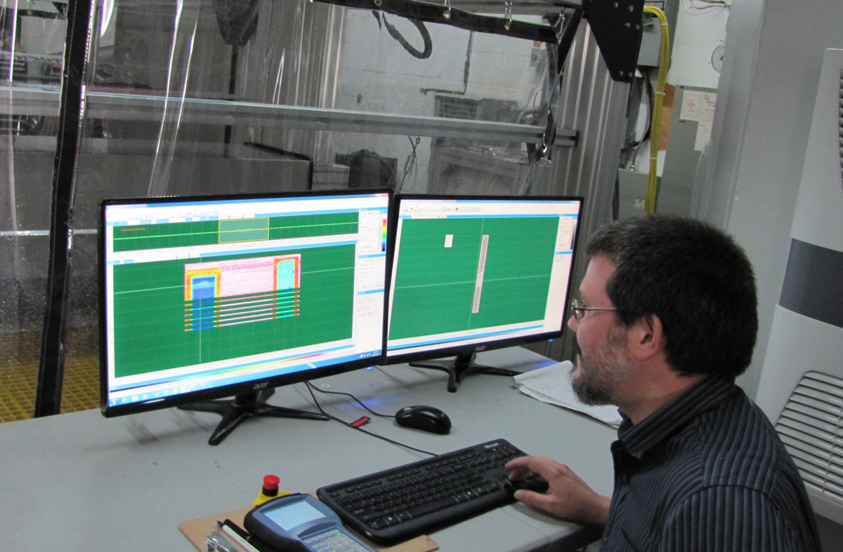
8 channel flatbed system for rapid inspection of large composite parts
One of the limitations of using multiple probes, which must be overcome, is the probes response uniformity within the array of probes. Array normalization tools are required to obtain a uniform response from all the probes and generate C-Scans that are equivalent to what would be obtained in a conventional single channel system.

Through-transmission C-Scan of 0-90° CFRP
Therefore, it is not the highest nor the lowest amplitude of a defect-free area that best represents the normal ultrasonic response from the material, but rather the average response. And so, if one tries to perform defect sizing based on the -6dB points using the maximum amplitude of a defect-free reference area from a composite structure with visible fibers in the C-Scan, the detected defects will be oversized. The following is an example of defect-oversizing situation in a woven composite structure, where a Teflon® insert of 25x25mm is detected and visible in the C-Scan (scan resolution of ~1.5 mm x 1.5 mm).

Defect-sizing using reference area maximum amplitude
The above result shows defect oversizing when we select the maximum amplitude to apply the 6dB drop sizing. The defect size was overestimated by ~20% on each side. A better approach consists of using the average amplitude of a local reference area, which represents the average response of the inspected structure. The following example shows a significant improvement and close to accurate sizing of the detected defect.

Defect-sizing using reference area average amplitude
Furthermore robust approach for defect-sizing in this situation, is to use the C-Scan Histogram in order to establish the appropriate reference amplitude level which represents the “normal” or median value of the amplitude response returned by the material.
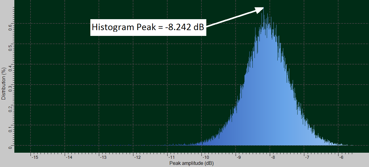
Histogram of C-Scan from ultrasonic testing of composite structure
The advantage of the Histogram approach over the average response of a selected reference area is to remove the inconsistency which may result from an improper selection of a reference area in the C-Scan by the operator. In addition, the Histogram approach is not affected by small variations in the C-Scan such as low amplitude indications from smaller defects, noise or amplitude drops caused by water jet scanning.

Defect-sizing using C-Scan Histogram