Grain Noise
If you are involved in the UT inspection of metals, and backscattered grain noise is making it difficult to reliably detect critical detects in some components, then this case study will be of special interest to you. It concerns the design of an improved UT inspection for aircraft engine rotor forgings. A quantifiable inspection goal is often stated in the following way: “I want to be able to reliably detect any defect that reflects sound at least as strongly as a number XXX calibration reflector. Flat-bottomed holes often serve as calibration reflectors, with a number XXX FBH being one having a diameter of XXX in units of 1/64thof an inch. Thus a number ½ FBH has a diameter of 1/128inches.
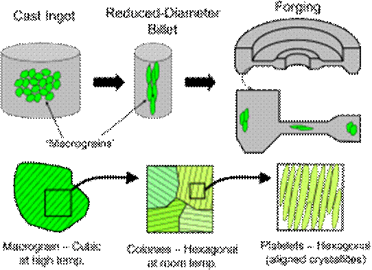
One common aircraft engine material is Ti 6-4 (mostly titanium with 6% aluminum and 4% vanadium by weight). As illustrated in the figure below it has a complicated microstructure which exhibits features on three major length scales. From largest to smallest, there are so-called macrograins, colonies and platelets. At the large end are the macrograins, namely large cubic crystallites which form as the molten metal solidifies. Upon further cooling these are mostly converted into a hexagonal phase, with many distinct hexagonal “colonies” forming from each macrograin. In this transition, certain closest-packed planes of atoms have to align, so for a given macrograin lattice there are 12 possible colony lattices. On a finer scale each colony consists of many platelets, or aligned hexagonal single crystals with a bit of the residual cubic phase in between. To make matters worse, these structures have their shapes changed by mechanical working as the cast ingot is first transformed into a reduced diameter billet, and again later as a slab from that billet is then forged into the desired shape.
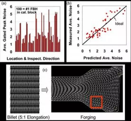
Within a given forging, backscattered grain noise levels vary considerably with position and inspection direction. One example of the degree of variation is shown in panel (a) below. There, small rectangular coupons were cut out of various regions from a forging, and UT C-scans were made to measure backscattered grain noise levels in each quadrant of each coupon (relative to a #1 FBH reference reflector in a calibration block). One sees about a factor of 5 variation in the grain noise level throughout the set of measurements. If one has sufficient information about the microstructural variations within the forging, one can use the grain noise models to predict the noise variations. One sees in panel (b) that much of the noise variability is explained by physical models which account for the scattering of macrograin/colony structures whose shapes and orientations are predicted by the metal flow computations of panel (c).
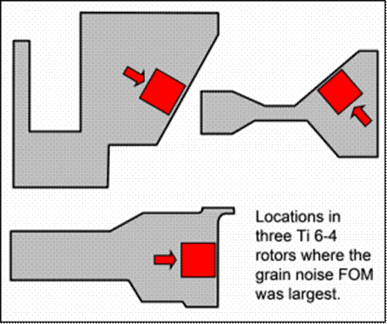
However, such complex model calculations are not required to design an adequate UT inspection. Rather, one can perform a cursory inspection of a forging to locate the high noise regions which will be most problematic to inspect. Then, guided by simple model concepts, one can acquire additional noise data from those regions and plot that in a manner that is best suited for inspection design. This is exactly what was done in an FAA-sponsored research program that partnered CNDE with three jet engine manufacturers (GE, Honeywell, and Pratt&Whitney). Each engine manufacturer supplied one representative forging, and through various measurements the high noise region for each was located as illustrated below.
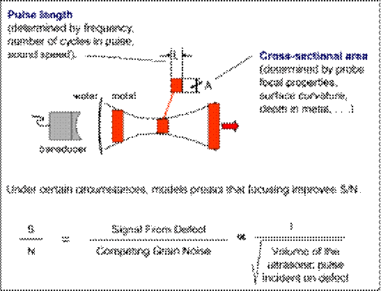
A sound pulse traveling through a metal occupies a physical volume. This volume changes with depth, being smallest in the focal zone. The volume, a product of a pulse length L and a cross-sectional area A, can be fairly easily measured by combining ultrasonic A-scans and C-scans, as will be seen shortly. For many cases of practical interest, the inspection simulation models predict that S/N is inversely proportional to the square root of the pulse volume at the depth of the defect. This is known as the “pulse volume rule-of-thumb” and has become a guiding principle for designing inspections. Generally speaking, it applies when both the grain size and the lateral size of the defect are smaller than the sound pulse diameter.
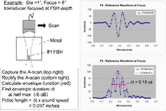
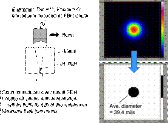
Simulation models can be used to predict pulse volumes, but it is also very straightforward to measure the pulse volume by scanning the transducer over a small reflector (so long as the reflector size is smaller than the beam diameter. The process is demonstrated in two steps in the figures below. Here a #1 FBH serves as small reflector. In the first step one moves the transducer laterally to maximize the reflected response from the hole. The A-scan is then acquired and its effective time duration is measured. From that a pulse length (in inches or centimeters) is computed. In the second step one scans the transducer in two-dimensions above the reflector, creating a standard C-scan. Since the beam diameter is larger that the reflector, the C-scan essentially displays an image of the sound pulse cross-section (or more accurately of the lateral profile of sound pressure squared). By a simple analysis of the C-scan, as illustrated, one can deduce an effective area. Multiplying the pulse length by the pulse area leads to a pulse volume. More technically, we are measuring a “response weighted pulse volume” which is the true measure that appears in the pulse-volume-rule-of-thumb (according to the models). The rule-of-thumb itself is obtained by beginning with the flaw response and noise models, and then making some rough approximations to greatly simplify the formulism.
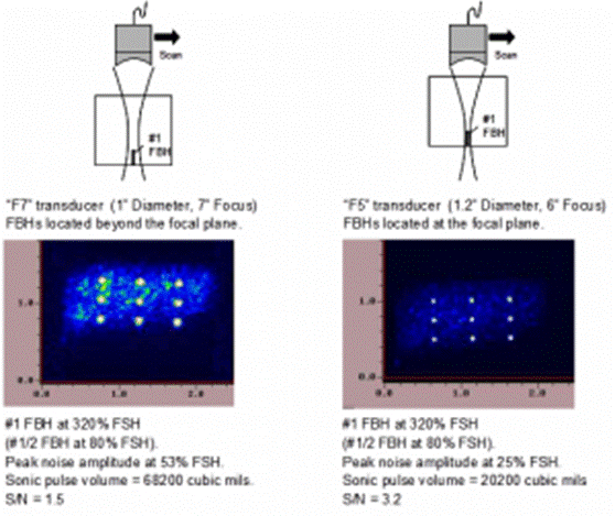
How does one make use of sonic pulse volume concepts to design an inspection? Begin by obtaining a specimen of the noisiest microstructure likely to be encountered in an inspection (e.g., our high-noise coupon from one of the engine forgings). One can drill a small FBH in that specimen itself, or use a FBH in a reference block having a similar sound speed and attenuation. Using several transducers with different degrees of focusing, one then measures both the pulse volume from the reference reflector and the backscattered grain noise level from test specimen (at the same depth as the FBH). For any given transducer, one can also vary the degree of focusing at the FBH by changing the water path, e.g., by focusing (in turn) in front of, on, and beyond the FBH target. The process is illustrated in the figure below. Once the noise level has been measured it can be divided by the peak response from the FBH to obtain a N/S ratio.
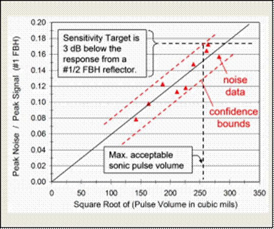
Once the pair of related values (sonic pulse volume and N/S) have been measured for various degrees of focusing, the values can be plotted as in the figure below. We choose to plot N/S versus the square root of the pulse volume, since the theory indicates that will result in a linear plot. Typically, the data plotted in this manner tends to roughly follow a straight line extending through the origin, with some statistical scatter about the best-fit line. From the plot one can then determine the maximum pulse volume required to meet inspection goals. In this case, the goal was to have the peak noise at least 3 dB below the response from a #½ FBH. As a #1 FBH was used as the reference reflector, allowance was made for the reflectivity differences between #1 and #½ FBHs (an expected factor of 4 difference). Without worrying too much about the math here, the result was that N/S as plotted below had to be less than about 0.17 to meet the inspection goal. That required a sonic pulse volume of about (250)-squared cubic mils. Thus the forging had to be inspected in such a manner that the sonic pulse volume was no larger than that value anywhere in the forging volume. Choosing transducers (either conventional or phased-array) which could be used to perform such an inspection, given the geometry of the forging, is another interesting topic. That is addressed by the last of the FAA citations in the reference section.