Time of Flight Diffraction Technique (TOFD)
Abstract
The article begins with an introduction of TOFD technique principles. The main part reviews some recent literature wherein excellent results for TOFD were obtained, especially regarding speed. The author gives examples of known problems when TOFD is used and recommends not discarding proven test methods in favor of the cost-saving factor of TOFD, however, TOFD can be a valuable add-on for other test methods.
Introduction
The first information on Time of Flight Diffraction Technique (TOFD) for ultrasonic testing on welds was introduced in 1977 [1]. The method was reported extensively in English publications and was also introduced in Germany [2]; nevertheless the method was more or less ignored by German NDT experts. Finally, in 1996, a European pre-standard was announced and thanks to that and some newly published papers [4-6] it seems that TOFD is on the way to replacing radiography and other UT techniques. One paper published in 1995 [7] referred to the wide acceptance of the method with a "TOFD Comes of Age" article.
|
The
following main principles describe TOFD:
|
|
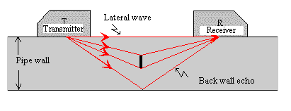
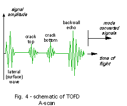
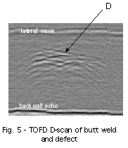
1. Two angle beam probes (usual 45°) are placed as a transmitter-receiver arrangement and are connected together (Fig 1). The distance of the probes is calculated according to the wall thickness. 2. Longitudinal waves are usually applied. The sound beam spread is large to maximize the extent of the scan. 3. The A-scan (Fig 4) [9] shows the so-called lateral wave, the back wall echoes and between both signals other signals can possibly appear, which can occur due to inhomogeneity. The A-Scan is not rectified in the TOFD technique. 4. TOFD technique is always applied with imaging methods (Fig 5) [9]. |
Fig 5 shows the B-Scan image generated by horizontal probe movement and sound time of flight in a vertical direction. The echo amplitude is displayed as gray scale, usually zero amplitude light gray (negative maximum amplitude black, positive maximum amplitude white). For weld testing it is important to notice that the probes are aligned transversal to the weld, while the image is generated in the direction of the weld. That means the image projection of Fig 5 stands perpendicular to the probe projection shown in Fig 1!
In practice, testing with the TOFD method is only applied by continuously moving the probe pair along the weld seam, while in traditional UT techniques the probe must be also moved perpendicular to the weld seam. Depending on the equipment the scan is performed either manually or by use of an automated manipulator. In any case a computerized data evaluation is necessary. In a very early stage of the TOFD method an instrument called "ZipScan" was applied, while today many instruments which can perform B-Scans can be used - many of those are available worldwide.
Three recent examples
As already mentioned TOFD weld testing was mainly applied outside Germany - here are three recent examples:
|
1. A platform in the North Sea was inspected for underwater welds of a repaired construction with a speed of 45 minutes for each. A radiography would need 16 to 29 hours [4]. 2. In West Java 2000 m welds on 8 gas containers, the test was carried out at a very high speed. Every day 60 - 100 m of welds were tested with TOFD /5/. 3. A report of the Netherlands welding institute (NIL) documented a higher probability of detection and lower test costs for the TOFD technique than other NDT methods [6]. So TOFD is twice as reliable than manual UT and by 1,3 more reliable than radiography. The latter is by 1,5 more expensive than TOFD. Besides flaw detection, TOFD can also perform sizing. |
Can TOFD perform all NDT tasks?
Does that mean that TOFD is a testing technique which can perform
all NDT tasks?
In the author's opinion the three most important drawbacks of TOFD are
described herein:
1. Sensitivity levelThe European pre-standard [3]
points out that TOFD only evaluates the time of flight and not the amplitude
of the diffracted echoes. Also for the TOFD technique it is necessary to define a gain or an amplitude level because the performed test always demands acceptance criteria. 2. Crack size determinationThe following case is described: A weld was tested during production according to AD-HP 5/3 with a sensitivity of detection of FBH 3 mm. That means that the weld possibly contains many inhomogeneities of FBH 1mm. In-service by use of the traditional angle beam testing can find a crack. The same crack can only be detected with a much higher gain setting if the TOFD technique is applied, since crack tip echoes respond with a very small amplitude in a range of FBH < 0,7 mm. In practice, diffracted echoes at crack tips are not so clear as they are displayed in Figs 4 and 5. Crack tip echoes are part of a noise area caused by other irrelevant diffracted echoes of inhomogeneity. That can make sizing with the TOFD technique impossible. A TOFD image inspector needs to perform depiction decisions similar to that used in radiography. He or she must distinguish the relevant echoes. 3. Detection of small cracks at backsideThis is one of the main disadvantages of TOFD. For in-service inspection of welds it is usually not so important to find old defects inside the weld seam. More important is the detection of cracks at the backside of containers or piping. As an inspection example defects of 0.5 mm depth and app. 10 mm length must be tested at a pressure component or container of 30 mm wall thickness The use of diffracted echoes is for that task is not possible. So close to the back wall the crack tip echo amplitude is very small. In that case traditional UT techniques with angle beam probes and use of the mirror effect must be applied . The TOFD technique is not applicable here! |
TOFD Weld testing Solutions
Advanced NDT TOFD Time Of Flight Defraction Inspection Weld testing ‐ High precision in sizing & monitoring of vertical discontinuities LMATS now has the tools and equipment to bring a whole new range of testing and detection capabilities to our customers.
LMATS offer TOFD Time Of Flight Defraction Weld Testing for:
· Weld root erosion testing in fluid carrying pipelines, high pressure steam pipes in power stations
· Fatigue crack sizing & monitoring to continue plant operation safely before reaching critical crack size
· Stress corrosion cracks & Creep cracks mapping & monitoring to continue plant operation safely before reaching critical crack size
Advanced NDT TOFD Time Of Flight Defraction ON SITE IMEDIATE RESULTS:
· Fast inspection of small- and large-diameter welds
· 100 % volumetric weld coverage
· Adaptable to butt welds, circumferential welds, long seams, one-sided access configuration, and most common weld profiles
· Inspection of wall thicknesses from 8 mm to 300 mm and part diameters from 100 m to flat
· Digital archiving of inspection data
· Fast and accurate sizing of discontinuities
· Portable for in-house and field inspections
· Improved productivity compared to radiography
· Improved probability of detection (POD) compared to radiography
· Combining Different Techniques for Full-Weld Coverage and Improved Efficiency.
LMATS are also able to identify trends (component and plant monitoring) for medium to long-term reliability and maintenance planning by using TOFD Time Of Flight Defraction testing methods.
LMATS regularly inspectusing TOFD Time Of Flight Defraction for welds in:
· Pressure Vessels
· High pressure steam pipes
· Fluid carrying pipelines
· Fatigue crack sizing.
LMATS Advanced NDT TOFD Time Of Flight Defraction Testing services covers the following industries but not limited to:
· Petro Chemical
· Gas
· Oil
· Energy Generation
· Transport
· Aerospace
· Marine
· Manufacturing
· Refrigeration
· and more.
Conclusion
Considering the limitations of the TOFD technique described above, discarding proven test methods in favor of the cost-saving factor of TOFD is not recommended, however, TOFD can be a valuable add-on for other test methods. Let's look at the example of the automated UT of welds for pipelines. By use of mechanized test systems like ROTOSCAN or PIPECAT it was possible to replace the radiography method. The latter uses 8 focused angle beam probes in pulse echo technique in as in conjunction with one probe pair for TOFD. Nobody would take the risk of using only the TOFD technique, however it is a valuable add-on for the complete test.