A-Scans and C-Scans
The ultrasonic inspection of metals for internal defects is similar in many respects to searching for fish using an ultrasonic fish finder. In each case a sonic transducer sends out a short-duration sound pulse and then “listens” for returning echoes. The defect is analogous to the fish, and the metal grains are analogous to weeds, rocks and other scatterers that can mask the presence of the fish.

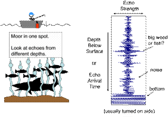
One common method of displaying “raw” ultrasonic data is termed an “A-scan”. There the transducer is fixed in position and one looks at the strength of the returning echoes as a function of time, or equivalently of penetration depth. In our fishing analogy, the boat is moored in one spot.
Another common data display type is an ultrasonic C-scan. There the transducer is scanned in two dimensions above the specimen being inspected. The display typically shows the peak response within a time or depth interval of interest as a function of transducer position. In our fishing analogy, the boat moves across the lake in raster search pattern.

B-Scan Ultrasonic testing
The
ultrasonic test is based on the reflection phenomenon of acoustic waves when
they meet obstacles to their spread. The wave is reflected back to its source,
if the obstacle is in a normal position in relation to the incident beam. These
phenomena are the base of the ultrasonic testing. The ultrasonic
conventional testing equipment is based on the principle to send a pulsed
ultra-high frequency ultrasonic testing beam from a hand-held transducer which
is placed on the surface of the object to be tested.
This wave is launched and then partially returns from spots with internal
imperfection or from the back wall of the material (background echo). The
returning sound is captured and analyzed, giving useful information that is
displayed on the ultrasonic testing equipment screen, showing the pulse amplitude
and the return time length to the transducer.
MANUAL SYSTEM
It
is a system in which the inspector is directly carrying out the examination,
i.e., he is responsible for the correct application of the inspection
procedures, including the head handling and the data interpretation.
The presentation of this result on the screen is called: A scan.
As shown in the image below:
B scan:
It is a graphical
presentation method of the results of a series of thickness measurements that
shows, in scale, the cross-section of the component or the inspected
part.
The B-Scan thicknesses tracking allows the location, identification and sizing
of thickness losses and cavities, providing a permanent record using a
printer or a video tape, and a mapping by means of planned view sketches.
AUTOMATED
/ MECHANICAL SYSTEM
It is a system where the inspector does not actuate during the test while this
one is automatically performed.
Actuation area: results interpretation
NOTE: The automatic system is related to the data processing method (computer)
and the mechanical one to the application method (Robots, equipment, ...).