Angle Beam Probe Selection
Angle Beam Probe Selection
 The various types of ultrasonic
transducers used in flaw detection applications were discussed in Section
4.1. In construction weld inspection, angle beam
probes are the primary tool, supplemented by straight beam transducers. Angle
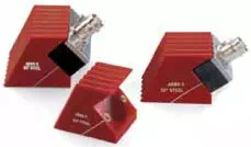
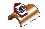
beam probes may be comprised of separate, interchangeable transducers and
wedges, or they may be integral assemblies. In many cases, the transducer/wedge
combination to be used for an inspection will be specified by a relevant code
or inspection procedure. If no probe has been specified, the inspector must
select one appropriate for the test at hand based on the following considerations.
The various types of ultrasonic
transducers used in flaw detection applications were discussed in Section
4.1. In construction weld inspection, angle beam
probes are the primary tool, supplemented by straight beam transducers. Angle
beam probes may be comprised of separate, interchangeable transducers and
wedges, or they may be integral assemblies. In many cases, the transducer/wedge
combination to be used for an inspection will be specified by a relevant code
or inspection procedure. If no probe has been specified, the inspector must
select one appropriate for the test at hand based on the following considerations.
 Frequency:
Angle beam transducers are generally available in frequencies from 500 KHz to 10 MHz, however most weld testing is performed at frequencies between 2 MHz and 5 MHz. Lower frequencies provide greater penetration across long sound paths or through coarse grained metal, while higher frequencies provide better resolution of small flaws. If not otherwise specified by code, 4 MHz or 5 MHz is usually a good frequency with which to begin an evaluation.
 Angle:
Almost all angle beam testing is performed at standard angles of 45, 60, and 70 degrees, although 30 degree and 90 degree (surface wave) wedges are also used in some specialized cases. As a general rule, higher angle wedges (60 and 70 degree) are commonly used when metal thickness is less than approximately 25 mm (1”), and lower angle wedges (45 degree) are commonly used when metal thickness is greater than approximately 50 mm (2”). Two or three different angles may be used in a given test based on part geometry and flaw resolution requirements. Further information can be found in common inspection codes. The wedge angle in a given case should be high enough that a first leg signal can reach the weld root from a position on the part surface that is not obstructed by the weld crown.

Size:
Angle beam transducers and wedges are available in a wide range of shapes and sizes, with round, square, or rectangular elements. North American industry practice favors the use of round elements (except in AWS code inspections), while European practice favors square or rectangular. The most common element sizes include 0.25”, 0.5”, and 1” diameter for round elements and 8x9 mm, 14x14 mm, and 20x22 mm for square/rectangular elements, however a number of other standard sizes are also available. Smaller elements can provide better resolution of small flaws, and smaller wedges can more easily conform to curved surfaces. Larger elements provide more area coverage and thus faster scanning, as well as reduced beam spreading across long sound paths.
 With these considerations in mind,
the inspector should use his/her knowledge and experience to select the optimum
probe or probes for a test. Where possible, probe performance should be
verified on test standards containing appropriate reference reflectors or known
defects.
With these considerations in mind,
the inspector should use his/her knowledge and experience to select the optimum
probe or probes for a test. Where possible, probe performance should be
verified on test standards containing appropriate reference reflectors or known
defects.
Common Test Practices
· Common Test Practices
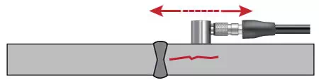
Scan patterns
In any ultrasonic test, the operator must move the transducer so as to cover the entire material volume that must be inspected, and also to cover the range of orientations needed to detect all likely flaws. While scan patterns should always be established with respect to specific test requirements, a common pattern is like this:
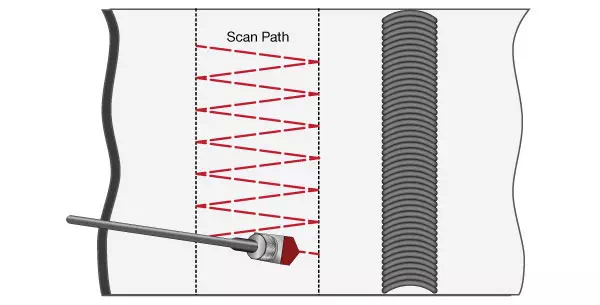
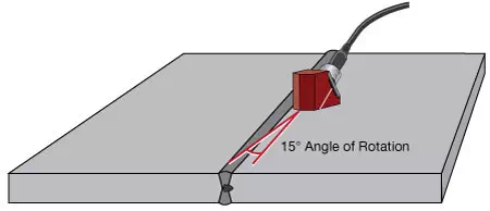
The probe is scanned back and forth between the surface point corresponding to a second leg test of upper part of the weld (left limit in drawing) and the point corresponding to a first leg test of the lower part of the weld (right limit). The wedge is angled slightly in alternate directions, and at each pass it is indexed by approximately one-half its width. This pattern provides full top-to-bottom coverage of the weld while insuring that there are no coverage gaps in the lateral direction, and the angulation helps in detection of inclusions, porosity, and other irregularly shaped reflectors. The test is then repeated from the other side of the weld.
When an indication is observed during this test, procedures may call for further scanning with probe rotation around the reflector and across an outside arc while aimed at the reflector. These motions help identify the type of reflector, as discussed in Section 6.6.
Some procedures also call for a scan along the length of the weld axis, with the wedge aimed slightly inward. The purpose of this scan is to identify transverse cracking in the weld zone, which may not be visible when the beam is directed perpendicular to the weld. Again the test is performed from both sides.
A final test is a straight beam examination of the heat affected zone on both sides of the weld to identify possible laminar cracks. This test typically uses a small diameter contact transducer to identify indications coming ahead of the backwall echo.
Positioning with respect to crown
As noted above, angle beam tests from the side of a weld typically require scanning the probe back and forth between the points where the beam hits the bottom of the weld (first leg) and the top of the weld (second leg). The corresponding points on each side of the weld can be marked with lines on the surface of the parts. Guides or templates can be fabricated to help maintain positioning, especially when performing a single-pass scan of the weld root or crown.
In some cases involving large wedges, relatively thin metal, and large crowns, it may not be possible to position the wedge close enough to the weld to optimize the first leg reflection from the weld root. In such cases a smaller wedge or a wedge designed with a short approach distance should be used. Alternately, testing can be performed in the second and third legs rather than first and second, but that may be less desirable due to attenuation and beam spreading effects.
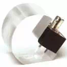
Contouring
Angle beam inspection of circumferential and axial welds in small diameter pipes and tubes can require contoured wedges for proper coupling. Contouring is generally recommended whenever the diameter becomes small enough that it becomes difficult to hold the wedge normal to the test piece, and/or when curvature significantly limits the area of the wedge in contact with the test piece on a convex radius, or creates a visible gap under the wedge on a concave radius. Typical wedge contours are shown below.
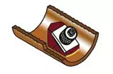
AID (Axial Inside Diameter)
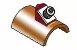
AOD (Axial Outside Diameter)
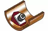
CID (Circumferential Inside Diameter)
COD (Circumferential Outside Diameter)