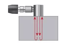
Straight Beam Tests
Straight beam testing is generally employed to find cracks or delaminations parallel to the surface of a test piece, as well as voids and porosity. It may use contact, delay line, dual element, or immersion transducers, all of which launch longitudinal waves on a straight path into the test piece. Common applications include testing plates, bars, forgings, and castings, as well as bolts and hanger pins and similar parts that can crack parallel to an accessible surface. Straight beam testing is also commonly employed in testing fiberglass and composites, as discussed in section 7.6.
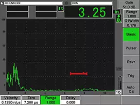
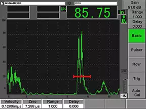
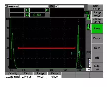
Like all other ultrasonic flaw detection techniques, straight beam testing utilizes the basic principle that sound energy traveling through a medium will continue to propagate until it either disperses or reflects off a boundary with another material, such as the air surrounding a far wall or the gap created by a crack or similar discontinuity. In this type of test, the operator couples the transducer to the test piece and identifies the echo returning from the far wall, as well as any fixed reflections originating from geometrical structures such as grooves or flanges. After noting the characteristic pattern of echoes derived from a good part, the operator then looks for any additional echoes that appear ahead of that backwall echo in a test piece, discounting grain scatter noise if present. An acoustically significant echo that precedes the backwall echo implies the presence of a laminar crack or void. Through further analysis, the depth, size, and shape of the structure producing the reflection can be determined.
No Flaw Present
Sound travels through material and reflects off backwall.
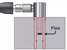
Flaw Present
- Some sound travels through entire material and reflects off the backwall, while some reflects off the intermediary flaw
- Echo amplitude correlates to flaw size

In the case of flat plates and smooth bars, this procedure is usually straightforward.
Straight beam testing can also be used to test braze joints and other bondlines that are oriented parallel to the surface. In these cases, even a good joint typically returns an echo since the braze metal or bonding material differs from the material being joined. However comparative testing will normally show that a lack of bonding returns an even larger echo, so the bondline echo amplitude is used as an indicator of the bond condition.
Angle Beam Inspection
While straight beam techniques can be highly effective at finding laminar flaws, they are not effective when testing many common welds, where discontinuities are typically not oriented parallel to the surface of the part. The combination of weld geometry, the orientation of flaws, and the presence of the weld crown or bead require inspection from the side of the weld using a beam generated at an angle. Angle beam testing is by far the most commonly used technique in ultrasonic flaw detection.
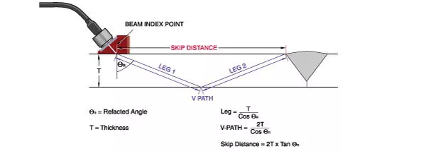
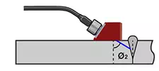
Angle beam probes consist of a transducer and a wedge, which may be separate parts or built into a single housing. They use the principle of refraction and mode conversion at a boundary to produce refracted shear or longitudinal waves in a test piece as shown below.
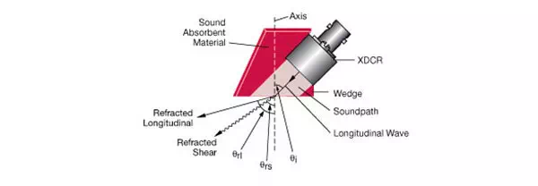
Most commonly used angle beam probes generate a refracted shear wave at standardized angles of 45, 60, or 70 degrees in the test material. The incident angle necessary to produce a desired refracted angle is based on material sound velocities and is calculated from Snell’s Law through the equation below.

In the typical case of a plastic or epoxy wedge coupled to steel, low incident angles will generate both longitudinal and shear wave beam components, and specialized longitudinal wave angle beam wedges do exist. However at commonly used inspection angles only a primary shear wave will be generated, since the L-wave solution to the equation would exceed 90 degrees, which is not possible.
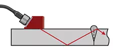
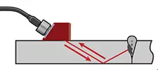
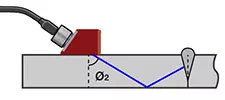
In typical inspections the sound beam will travel at the generated angle down to the bottom of the test piece and then reflect upward at the same angle. Moving the probe back and forth causes the sound beam to sweep across the full height of a weld. This scanning motion enables inspection of the entire weld volume and detection of discontinuities both at the fusion lines and within the weld body.
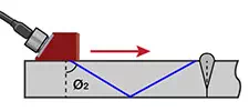
As in the case of straight beam testing, in angle beam testing the operator looks for reflections corresponding to discontinuities. During initial setup the operator must note any echoes that originate from weld bead or other geometric structures. Additional echoes appearing within the zone representing the weld would correspond to a lack of fusion, cracking, porosity, or other discontinuities whose type, depth, and size can be determined through further analysis.
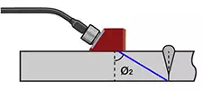
In the example below, the sound beam passes through a good weld without reflecting back, and no significant indications are seen on the screen. A discontinuity within the weld zone, however, causes a strong reflection with the zone of interest marked by the red gate.