|
Continuous and Residual Magnetization Techniques In magnetic particle inspection, the magnetic particles can either be applied to the component while the magnetizing force is applied, or after it has been stopped. Continuous magnetization describes the technique where the magnetizing force is applied and maintained while the magnetic particles are dusted or flowed onto the surface of the component. In a wet horizontal testing unit, the application of the particles is stopped just before the magnetizing force is applied; but, since particles are still flowing over and covering the surface, this is considered continuous magnetization. Residual magnetization, on the other hand, describes the technique where the magnetizing force is applied to magnetize the component and then stopped before applying the magnetic particles. Only the residual field of the magnetized component is used to attract magnetic particles and produce an indication.
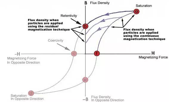
The continuous technique is generally chosen when maximum sensitivity is required because it has two distinct advantages over the residual technique. First, the magnetic flux will be highest when current is flowing and, therefore, leakage fields will also be strongest. Field strength in a component depends primarily on two variables: the applied magnetic field strength and the permeability of the test object. Viewing the upper right portion of the hysteresis loop below, it is evident that the magnetic flux will be the strongest when the magnetizing force is applied. If the magnetizing force is strong enough, the flux density will reach the point of saturation. When the magnetizing force is removed, the flux density will drop to the retentivity point. The two gray traces show the paths the flux density would follow if the magnetizing force was applied and removed at levels below that required to reach saturation. It can be seen that the flux density is always highest while the magnetizing current is applied. This is independent of the permeability of a material.
However, the permeability of the material is very important. High permeability materials do not retain a strong magnetic field so flux leakage fields will be extremely weak or nonexistent when the magnetizing force is removed. Therefore, materials with high magnetic permeability are not suited for inspection using the residual technique. When the residual technique is used to inspect materials with low permeability, care should be taken to ensure that the residual field is of the necessary strength to produce an indication. Defects should be relatively large and surface breaking to have a high probability of detection using the residual method. The second advantage of the continuous technique is that when current is used to generate the magnetizing force, it can provide added particle mobility. Alternating or pulsed direct current will cause the particles to vibrate and move slightly on the surface of the part. This movement allows the particles to travel to leakage sites. More particles mean brighter indications compared to those formed using the residual technique. One disadvantage of the continuous method is that heating of the component occurs when using direct magnetization. For example, when prods are used, they may create areas of localized heating when the continuous technique is used. This may be acceptable on components that will be further processed (removing this condition), but machined or in-service components may be adversely affected by this condition. While generally not recommended, the residual technique does have its uses. It is commonly used in automated inspection systems to inspect materials with high retentivity. To speed throughput, automated systems often magnetize the parts and then submerge them in an agitated magnetic particle bath or pass them through a spray station. Closely controlled automated systems provided good results using the residual magnetism technique. |
||
|
|
||
|
Field Direction and Intensity Field Direction Depending on the application, pie gages, QQI's, or a gauss meter can be used to check the field direction. The pie gage is generally only used with dry powder inspections. QQI shims can be used in a variety of applications but are the only method recommended for use in establishing balanced fields when using multidirectional equipment. Field Strength
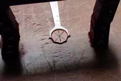
Formulas for calculating current levels should only be used to estimate current requirements. The magnetic field strength resulting from calculations should be assessed for adequacy using one of the two method discussed above. Likewise, published current level information should also be used only as a guide unless the values have been established for the specific component and target defects of the inspection at hand. Using a Pie Gage A pie gage is placed copper side up and held in contact with the component as the magnetic field and particles are applied. Indications of the leakage fields provide a visual representation of defect direction within the component. Pie gages work well on flat surfaces, but if the surface is concave or convex, inaccurate readings may occur. The pie gage is a flux sharing device and requires good contact to provide accurate readings.
Using Quantitative Quality Indicator (QQI) Shims Quantitative Quality Indicator (QQI) flaw shims are used to establish proper field direction and to ensure adequate field strength during technique development. The QQI flaw shim is the most efficient means of determining balance and effectiveness of fields. The QQI's are also flux sharing devices and must be properly attach so as not to allow particles to become trapped under the artificial flaw. Application using Super glue is the preferred way of attaching the artificial flaw, but does not allow for reuse of the shims. Shims can also be attached with tape applied to just the edge of the shim. It is recommended that the tape be impervious to oil, not be fluorescent, and be 1/4 to 1/2 inch in width. The QQI must be applied to locations on the component where the flux density may vary. One example would be the center area of a yoke or Y shaped component. Oftentimes, the flux density will be near zero in this area. If two legs of a Y are in contact with the pad in circular magnetization, it must be determined if current is flowing evenly through each leg. A QQI on each leg would be appropriate under such conditions. QQI's can be used to establish system threshold values for a defect of a given size. By attaching a QQI shim with three circles (40%, 30% and 20% of shim thickness) to the component, threshold values for a specific area of the component, can be established. Begin by applying current at a low amperage and slowly increasing it until the largest flaw is obtained. The flux density should be verified and recorded using a Hall effects probe. The current is then increased until the second circle is identified and the flux density is again recorded. As the current is further increased, the third ring is identified and the current values are recorded.
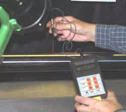
Hall Effects Gauss Meter
There are several types of Hall effects probes that can be used to measure the magnetic field strength. Transverse probes are the type most commonly used to evaluate the field strength in magnetic particle testing. Transverse probes have the Hall effect element mounted in a thin, flat stem and they are used to make measurements between two magnetic poles. Axial probes have the sensing element mounted such that the magnetic flux in the direction of the long axis of the probe is measured. To make a measurement with a transverse probe, the probe is positioned such that the flat surface of the Hall effect element is transverse to the magnetic lines of flux. The Hall effect voltage is a function of the angle at which the magnetic lines of flux pass through the sensing element. The greatest Hall effect voltage occurs when the lines of flux pass perpendicularly through the sensing element. If not perpendicular, the output voltage is related to the cosine of the difference between 90 degrees and the actual angle. The peak field strength should be measured when the magnetizing force is applied. The field strength should be measured in all areas of the component to be inspected. |
||
|
|
||