Pulsed Eddy Current Inspection
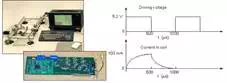
Conventional eddy current inspection techniques use sinusoidal alternating electrical current of a particular frequency to excite the probe. The pulsed eddy current technique uses a step function voltage to excite the probe. The advantage of using a step function voltage is that it contains a continuum of frequencies. As a result, the electromagnetic response to several different frequencies can be measured with just a single step. Since the depth of penetration is dependent on the frequency of excitation, information from a range of depths can be obtained all at once. If measurements are made in the time domain (that is by looking at signal strength as a function of time), indications produced by flaws or other features near the inspection coil will be seen first and more distant features will be seen later in time.
To improve the strength and ease interpretation of the signal, a reference signal is usually collected, to which all other signals are compared (just like nulling the probe in conventional eddy current inspection). Flaws, conductivity, and dimensional changes produce a change in the signal and a difference between the reference signal and the measurement signal that is displayed. The distance of the flaw and other features relative to the probe will cause the signal to shift in time. Therefore, time gating techniques (like in ultrasonic inspection) can be used to gain information about the depth of a feature of interest.
The use of pulsed eddy currents has long been considered for testing metals (Libby, 1971) and it has been applied to operations in specialized areas, such as in the nuclear energy industry, where testing equipment is often constructed to order. However, significant progress in this direction has taken place only recently after appropriate advances in technology (Krzwosz et al. 1985; Sather, 1981; Waidelich, 1981; Wittig and Thomas 1981), but at the time of writing, commercial equipment was not yet available. The method has the potential advantages of greater penetration, the ability to locate discontinuities from time-of-flight determinations, and a ready means of multi-frequency measurement. At present, it does not generally have the precision of the conventional methods. The apparatus is somewhat complicated in design and not readily usable by the average operator who is experienced with the conventional eddy current equipment. Its main successes are in the testing of thin metal tubes and sheets, as well as metal cladding for measuring thickness and for the location and sizing of internal defects.
When comparing the pulsed method with the conventional eddy current technique, the conventional technique must be regarded as a continuous wave method for which propagation takes place at a single frequency or, more correctly, over a very narrow frequency bandwidth. With pulse methods, the frequencies are excited over a wide band, the extent of which varies inversely with the pulse length; this allows multi-frequency operation. As found with ultrasonic testing, the total amount of energy dissipated within a given period of time is considerably less for pulsed waves than for continuous waves having the same intensity. For example, with pulses containing only one or two wavelengths and generated 1000 times per second, the energy produced is only about 0.002 of that for continuous waves having the same amplitude. Thus, considerably higher input voltages can be applied to the exciting coil for pulsed operation than for continuous wave operation.
Pulsed waves can reasonably be expected to allow penetration of measurable currents through a metal sample to a depth of about 10 times the standard penetration depth, provided a suitable probe is used (i.e. a shielded ferrite-cored coil, see section 5.3). Therefore, penetration is possible through a 2 mm thick plate at frequencies of 1-3 kHz for non-ferromagnetic metals having corresponding electrical conductivities ranging from 60 down to 20MS/m. However, with an unmagnetized steel plate 2 mm thick, where sigma = 5 MS/m and µr = 100, the maximum frequency for through-penetration is only 100 Hz.
Pulsed eddy currents may be generated by a thyratron connected in series with the exciting coil through a capacitor (e.g. Waidelich, 1981). A direct voltage, on the order of 1200 V, slowly charges the capacitance and when the thyratron conducts there is an abrupt discharge through the coil in which free-damped harmonic oscillations occur. This is repeated periodically (i.e. at 1 kHz), so as to propagate the eddy current pulses through the metal.
The currents are detected by a receiving probe located either adjacent to or on the opposite side of the metal sample from the exciting probe when access is possible. The range of propagated frequencies depends on the logarithmic decrement of the exciting circuit, and because the speed of the waves is a function of frequency, dispersion takes place and the pulse changes in shape as it progresses through the metal. As one would expect, the height of the peak and its time delay can be related to the thickness of the metal. Waidelich reports a maximum penetration of 90 mm foraluminum sheet and 10 mm for steel. For 6 mm thick sheets, the peak value of the received pulse voltage was 13 V for aluminum but only 20 mV for steel. Krzwosz et al. (1985) has shown how pulses that result from the presence of internal simulated defects produce broadening with an increase in depth.
The frequency content of the pulses depends on their lengths, and in the extreme, contains continuous spectra ranging from less than 100 Hz to 1 or 2 kHz. By performing a Fourier transformation, the pulse obtained by the receiving probe can be displayed in the form of the variation of amplitude (or phase) with frequency. By sampling different delay times within a pulse, different parts of the spectrum can be evaluated (Sather, 1981). If both amplitude and phase are measured, two parameters (i.e. presence of defects, variations in tube thickness, and changes in fill-factor or liftoff) can be evaluated for each frequency selected in the same way as with the multi-frequency method, although, at present, with a lower degree of precision.
Dodd et al.(1988) has designed and developed a pulsed magnetic saturation method for the eddy current testing of ferromagnetic metals. The DC field pulses are generated by passing a high-current pulse through an electromagnet so as to produce saturation in the metal object; the pulse length is made equal to the thickness of the object, thus ensuring complete eddy current penetration where feasible. The DC pulse, on the order of 1 ms duration, simultaneously produces an eddy current pulse, which is detected by a probe; the output of the probe is characteristic of the material being tested.
This technique has the advantage of producing high magnetic peak powers with low average powers, thus keeping any heating of the test sample down to an acceptable level. It has been applied successfully to the internal testing of the walls of steel steam generator tubes, and tubes of diameter 10.9 mm and wall thickness 5 mm have been examined with peak powers of 500 kW. Small defects close to the external surfaces can be detected, and by taking advantage of the multi-frequency properties of pulsed eddy currents, their indications can be resolved from those that originate from other characteristics of the tubes.
More recent work on the use of pulsed eddy currents has been reported by Gibbs and Campbell (1991), who inspected cracks under fasteners in aluminum aircraft structures. Here, a Hall element was used as a receiver. Radial position, approximate depth, and relative size of defects hidden under fastener heads could be determined in countersunk areas for defect depths of up to 7 mm for nonferrous fasteners and 14 mm for ferrous fasteners.
Lebrun et al. (1975) reported the detection of deep cracks in ferromagnetic samples using an emission coil excited by square pulses of high intensity and employing highly sensitive magneto-resistive sensors to measure the resultant magnetic fields. Defects of 1 mm x 1 mm could be detected at a depth of 5 mm and 3 mm x 4 mm at a depth of 20 mm